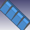
From the beginning I wanted to build a vertically running wind turbine since it does not have to be oriented towards the wind. A vertical turbine usually starts at low wind speeds and withstand strong winds.
For vertical turbines there are several popular approaches, such as the Darrieus rotor, the Savonius rotor and various modifications.
Since I do not have the tools and possibilities of a production company as a private person, the rotor should be as simple as possible from the structure, so that I am able to implement it from home.
After much research on the net, I found an Excel list for dimensioning a Lenz2 rotor.
According to the inventor of the wing profile, it has a quite high efficiency, with manageable construction complexity.
Now, where it was clarified, what kind of rotor it should become, the dimensions had to be determined.
As can be inferred from this study, the average wind speed in Saxony is 10 meters above the ground at approx. 5 m / s.
My windmill is about 4 – 5 meters above the ground and at a distance of about 10 meters there are a few bushes, which surmount the wind wheel.
So the 5 m / s average wind speed is not achievable.
My assumption is an average wind speed of 3m / s, which would be immediately the end for a location for a productive plant.
But unfortunately I don’t have a beach property with 10 meters high mast available.
The wind turbine is supposed to feed a significant output of more than 10 KW / h per year into the battery. This is much more than I could generate in 2012 with my small solar cells.
I’ve played a little with the Excel list for the dimensioning of Lenz2 rotors around and I decided at the end for 70cm diameter and 70cm height with 3 wings.
This corresponds to almost half a square meter area where air flows through.
If I assume the 2.65 watts, which can be generated with the 70/70 rotor at average 3m / s within a year, I come to 23.2 KWh per year. This is equivalent to 3.5 times my electricity generation from 2012.
| Calculated output (according to Lenz) | ||||
|---|---|---|---|---|
| Wind speed km/h | Wind speed m/s | Speed loaded rpm | Speed idle rpm | Electrical power in W |
| 4 | 1 | 22 | 44 | 0,10 |
| 7 | 2 | 44 | 87 | 0,79 |
| 11 | 3 | 65 | 131 | 2,65 |
| 14 | 4 | 87 | 175 | 6,29 |
| 18 | 5 | 109 | 218 | 12,28 |
| 22 | 6 | 131 | 262 | 21,22 |
| 25 | 7 | 153 | 306 | 33,70 |
| 29 | 8 | 175 | 349 | 50,30 |
| 32 | 9 | 196 | 393 | 71,62 |
| 36 | 10 | 218 | 437 | 98,25 |
| 40 | 11 | 240 | 480 | 130,77 |
| 43 | 12 | 262 | 524 | 169,78 |
| 47 | 13 | 284 | 567 | 215,86 |
| 50 | 14 | 306 | 611 | 269,60 |
| 54 | 15 | 327 | 655 | 331,59 |
| 58 | 16 | 349 | 698 | 402,43 |
| 61 | 17 | 371 | 742 | 482,70 |
| 65 | 18 | 393 | 786 | 573,00 |
| 68 | 19 | 415 | 829 | 673,90 |
| 72 | 20 | 437 | 873 | 786,00 |
| 76 | 21 | 458 | 917 | 909,90 |
| 79 | 22 | 480 | 960 | 1.046,17 |
| 83 | 23 | 502 | 1004 | 1.195,41 |
| 86 | 24 | 524 | 1048 | 1.358,21 |
| 90 | 25 | 546 | 1091 | 1.535,16 |
| 94 | 26 | 567 | 1135 | 1.726,85 |
| 97 | 27 | 589 | 1179 | 1.933,86 |
| 101 | 28 | 611 | 1222 | 2.156,79 |
| 104 | 29 | 633 | 1266 | 2.396,22 |
| 108 | 30 | 655 | 1310 | 2.652,76 |
| 112 | 31 | 677 | 1353 | 2.926,97 |
| 115 | 32 | 698 | 1397 | 3.219,46 |
| 119 | 33 | 720 | 1441 | 3.530,82 |
| 122 | 34 | 742 | 1484 | 3.861,63 |
| 126 | 35 | 764 | 1528 | 4.212,48 |
| 130 | 36 | 786 | 1572 | 4.583,96 |
| 133 | 37 | 808 | 1615 | 4.976,67 |
| 137 | 38 | 829 | 1659 | 5.391,19 |
| 140 | 39 | 851 | 1702 | 5.828,11 |
| 144 | 40 | 873 | 1746 | 6.288,01 |
| Rotor diameter: | 0,7 m |
| Rotor height: | 0,7 m |
| Number of blades: | 3 pcs |
| Efficiency according to Lenz: | 41 % |
| Efficiency generator: | 80 % |
The 2.65 watts are, however, also the lower end of the scale as far as power generation is concerned.
The generator should perform well in the speed range 60 – 500 rpm.
Typically, the power that can be delivered should increase as described in the table.
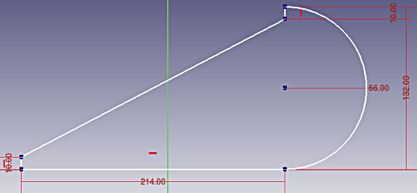
| Radius of the slats: | 66 mm |
| Length entire blade: | 280 mm |
A look at the back of the table, but also shows what can work beyond the 15m / s for forces.
On one site, the wind turbine does not provide much more than 20 KW / h per year, but the design must be stable enough to withstand several thousand watts of wind power.
The lighter the construction is, the better.
It is relatively easy to see that such a project has a certain claim.
I have decided to use aluminum for the construction of the rotor, since this on the one hand it is a lightweight material and on the other has not to be protected against corrosion.
Aluminum is available anodised. I chose brown colored metal sheets, because it dark colors are reflecting very little sunlight from my point of view.
Naked aluminum looks like a mirror and I do not want to risk that the neighbors will be disturbed by sunshine reflections.
Except for the mast, I trust glue and screw connections.
The wing profiles are glued with UHU Endfest 300 (300 Kg / cm² adhesive force).
The connections up to the hub are screwed so that there is the possibility to align the rotor, since at relatively high revolutions a unbalance would lead to problems.
The structure in detail I will explain in the following pages (see page navigation – top right of the page).
And finally the drawing of the profile started with the project 2011:


