Categories
Arduino

Arduino – MCP42010 controlling several digital potentiometers in cascade

Arduino – MCP42010 – Example of controlling several digital potentiometers

After the example Arduino – control and test digital potentiometer MCP42010 on breadboard and the graphic variant Node Red – Arduino – control digital potentiometer MCP42010 I tested the control of 2 digital potentiometers MCP42010 cascaded.

circuit


Control of the two MCP42010

The control of the primary MCP42010 is described in detail in Arduino – Control and Test Digital Potentiometer MCP42010 on breadboard.
Write in potentiometer 1 -> B00010001 and in potentiometer 2 -> B00010010
The value that the selected potentiometer should set is transmitted as the second byte.

To reach the second MCP42010, 4 bytes have to be sent instead of 2 bytes for a single one.
With three MCP42010 6 bytes are required, with four 8 bytes and so on.
In order to control a potentiometer of the second MCP42010 directly without changing the contents of the first chip, two more bytes with the value 0 are sent.
See also the picture on the left from the data sheet.

Write in potentiometer 3 -> B00010001 value B00000000 B00000000
Write in potentiometer 4 -> B00010010 value B00000000 B00000000

The whole thing has to be read from right to left.
4 bytes are written, or better shifted into it.
The first two bytes (from the left) are shifted from the following two bytes into the second MCP42010.
Two bytes with ‘zero’ arrive in the first MCP42010, i.e. no changes to the values in the 1st chip.

Here is a minimal example of how the value 127 is loaded into potentiometer 1 (Pot0) of the second MCP42010.

Categories
Python

Raspberry Pi – Access to WordPress with Python wordpress-api

Would not it be nice if the Raspberry Pi could create articles on my website, modify them and become an editor?
If you use WordPress on your website, it’s relatively easy, since WordPress from version 4.8 includes the REST interface as standard and there is a corresponding plugin for older versions.

Whether the interface is available, can be easily detected by attaching ‘wp-json’ to the URL for each WordPress web page. For example, http://www.henrykoch.de/wp-json should display a Json string in the browser:

"name":"www.HenryKoch.de","description":"","url":"http:\/\/www.henrykoch.de","home":"http:\/\/www.henrykoch.de\/de","gmt_offset":2,"timezone_string":"Europe\/Berlin"

Installation python wordpress-api

For the installation of the WordPress Api for python, I am followed this guide https://pypi.python.org/pypi/wordpress-api/1.2.2, which did not work immediately.
To get the API running, additional packages had to be installed.

So I came to the result (On the Raspberry Pi)

sudo apt-get update
sudo apt-get install libxml2-dev
sudo apt-get build-dep python3-lxml
pip install wordpress-api

Libxml and lxml were missing from me.

Authentication

I spent a lot of time here.
I really wanted an OAuth authentication and I failed with the described REST oauth1 plugin.
After a long back and forth I installed this plugin: WP OAuth Server

As seen on the pictures, there is an OAuth server entry after installation on the dashboard on the left side. There I created a user. If this is done, the user is listed and a client ID is specified. Consumer_key in the phthon script
In addition, the Secret Key can now be displayed -> consumer_secret in the python script.

first test script

#!/usr/bin/python
# -*- coding: utf-8 -*-
from wordpress import api as wpapi
from wordpress import API
 
wpapi = API(
    url="http://ai.henrykoch.de/", #your URL
    consumer_key="xxxxxxxxxxxxx", #your key
    consumer_secret="xxxxxxxxxxxxx", #your secret key
    api="wp-json",
    version="wp/v2",
    wp_user="xxx",    #your wp User
    wp_pass="xxx"     #wp users password
)
r = wpapi.get("posts")
print r.status_code
print r.headers['content-type']
print r.encoding
print r.text
print r.json()

The result

pi@raspberrypi:~/python/Wordpress $ python myscript.py
200
application/json; charset=UTF-8
UTF-8
[{"id":1,"date":"2017-08-08T15:25:58","date_gmt":"2017-08-08T13:25:58","guid":{"rendered":"http:\/\/ai.henrykoch.de\/?p=1"},"modified":"2017-08-08T15:38:46","modified_gmt":"2017-08-08T13:38:46","slug":
...
Categories
Node Red

Arduino – Node Red – MCP42010 control the digital potentiometer

Arduino – Node Red – MCP42010 – Sample control of the digital potentiometer

In the article Arduino – control and test digital potentiometer MCP42010 on a breadboard I showed how the MCP42010 can be controlled via the serial monitor of the Arduino IDE.
Now I want to do this more comfortably.
The operation has to take place from the browser, should look visually very appealing and it must also be possible with the smartphone.

Why with Node Red?

Node Red is included in the standard installation of the Raspberry Pi, free and intuitive to use.
By the possibility of clicking together the flow by drag and drop together, one comes very quickly to a good result.
For prototypes and also IOT applications this is a really great thing.
Where light is, is also shadow: Node Red consumes quite a lot of resources.
Nevertheless, the Raspberry Pi 2 does well and the performance with the Pi 3 should still much better.

Required functions of the flow

The flow is supposed to take over the entries, which I have done by hand in the Arduino – control and test digital potentiometer MCP42010 on a breadboard.
The flow should represent the return values in a Gauge Chart.

data input:
1:Value between 0-255
-> sets potentiometer1 to the value and returns the voltage to A0
2:Value between 0-255
-> sets potentiometer2 to the value and returns the voltage to A1

The Flow

  • copy the following flow and insert it under menu (top right) -> Import – Clipboard
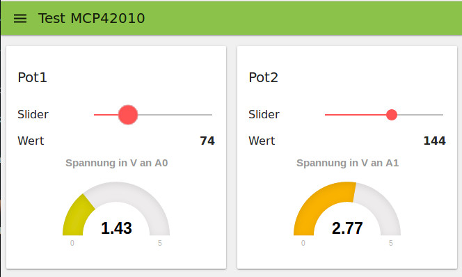
[{"id":"ebf0e947.110038","type":"ui_slider","z":"8ec3bd3.cce4dc","tab":"147200e2.b8e19f","name":"Slider","topic":"","group":"Pot1","order":1,"min":0,"max":"255","x":225.5,"y":125,"wires":[["25bd2695.9acaf2"]]},{"id":"b755b484.2bd75","type":"ui_text","z":"8ec3bd3.cce4dc","tab":"147200e2.b8e19f","name":"Wert","group":"Pot1","order":1,"format":"{{msg.payload}}","x":636.5,"y":102,"wires":[]},{"id":"ed9f01b2.dfae38","type":"ui_gauge","z":"8ec3bd3.cce4dc","tab":"147200e2.b8e19f","name":"Spannung in V an A0","group":"Pot1","order":1,"format":"{{value}}","min":0,"max":"5","x":681.5,"y":322,"wires":[]},{"id":"25bd2695.9acaf2","type":"function","z":"8ec3bd3.cce4dc","name":"Value to Command","func":"var msg1 = { payload:\"1:\" + msg.payload +\"\\n\"};\nreturn [msg, msg1];","outputs":"2","noerr":0,"x":440.5,"y":125,"wires":[["b755b484.2bd75"],["134514.6c0042ed"]]},{"id":"134514.6c0042ed","type":"serial out","z":"8ec3bd3.cce4dc","name":"/dev/ttyUSB0","serial":"d535ccdc.123838","x":658.5,"y":148,"wires":[]},{"id":"13db30d1.da3c67","type":"serial in","z":"8ec3bd3.cce4dc","name":"/dev/ttyUSB0","serial":"43aa993f.185738","x":186.5,"y":345,"wires":[["f39416bc.0495"]]},{"id":"f39416bc.0495","type":"function","z":"8ec3bd3.cce4dc","name":"Response to value","func":"//find A0 or A1\nvar value;\nif (msg.payload.indexOf(\"A0\") != -1) {\n    value = msg.payload.split(\"A0: \");\n    value = value[1].replace(\" Volt\", \"\");\n    msg.payload = value;\n    return [msg, null];\n} else {\n    value = msg.payload.split(\"A1: \");\n    value = value[1].replace(\" Volt\", \"\");\n    msg.payload = value;\n    return [null , msg];\n}","outputs":"2","noerr":0,"x":431.5,"y":345,"wires":[["ed9f01b2.dfae38"],["ddbfff6.2bdb3"]]},{"id":"8a48ef7d.33ba9","type":"ui_slider","z":"8ec3bd3.cce4dc","tab":"147200e2.b8e19f","name":"Slider","topic":"","group":"Pot2","order":1,"min":0,"max":"255","x":224,"y":227,"wires":[["127d632d.c0419d"]]},{"id":"5a58be54.e6b8d8","type":"ui_text","z":"8ec3bd3.cce4dc","tab":"147200e2.b8e19f","name":"Wert","group":"Pot2","order":1,"format":"{{msg.payload}}","x":635,"y":204,"wires":[]},{"id":"127d632d.c0419d","type":"function","z":"8ec3bd3.cce4dc","name":"Value to Command","func":"var msg1 = { payload:\"2:\" + msg.payload +\"\\n\"};\nreturn [msg, msg1];","outputs":"2","noerr":0,"x":439,"y":227,"wires":[["5a58be54.e6b8d8"],["ee1b0407.9fbca"]]},{"id":"ee1b0407.9fbca","type":"serial out","z":"8ec3bd3.cce4dc","name":"/dev/ttyUSB0","serial":"43aa993f.185738","x":657,"y":250,"wires":[]},{"id":"ddbfff6.2bdb3","type":"ui_gauge","z":"8ec3bd3.cce4dc","tab":"147200e2.b8e19f","name":"Spannung in V an A1","group":"Pot2","order":1,"format":"{{value}}","min":0,"max":"5","x":681,"y":370,"wires":[]},{"id":"147200e2.b8e19f","type":"ui_tab","z":"","name":"Test MCP42010","icon":"dashboard","order":"1"},{"id":"d535ccdc.123838","type":"serial-port","z":"","serialport":"/dev/ttyUSB0","serialbaud":"9600","databits":"8","parity":"none","stopbits":"1","newline":"\\n","bin":"false","out":"char","addchar":false},{"id":"43aa993f.185738","type":"serial-port","z":"","serialport":"/dev/ttyUSB0","serialbaud":"9600","databits":"8","parity":"none","stopbits":"1","newline":"\\n","bin":"false","out":"char","addchar":false}]
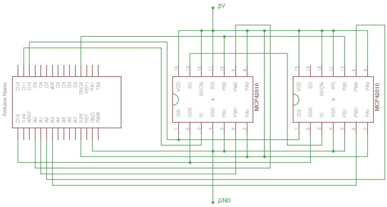
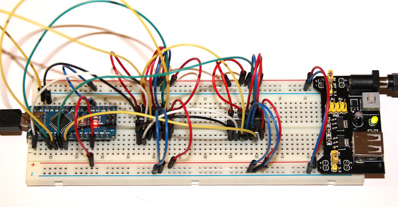
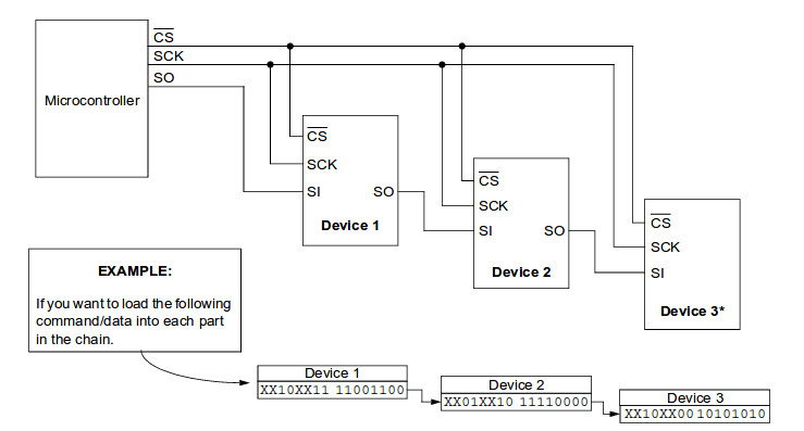
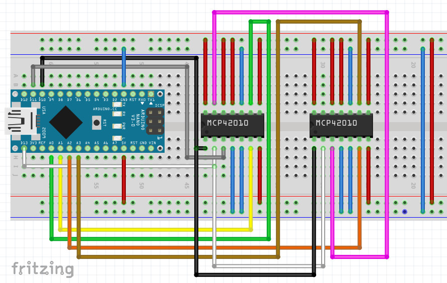
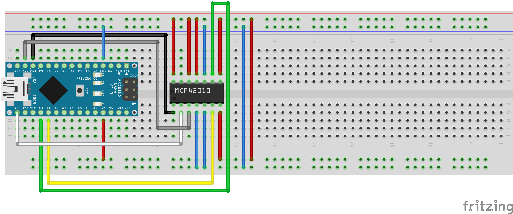
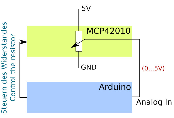
Video Controlling MCP42010 with Node Red

Categories
Arduino

Arduino MCP42010 – control and test the digital potentiometer

Arduino MCP42010 – test on a breadboard

There are many instructions to control digital potentiometers with an Arduino. The search for the MCP42010, was very promising, but led to success only after several attempts. Many web pages and foren entries discuss the topic, but in the end they do not come to a working solution.

The idea is to switch the two digital 10 kilohms potentiometers at the ends between 5 volts and ground and place the center of each potentiometer on an individual analog input.
Depending on what now for a resistor controlled, the voltage at the analog inputs will rise or fall. And this can be evaluated.

I describe how I proceeded.

I’ve been used an Arduino Nano replica, which is already available for a little more than 3.50 Euros, and a digital potentiometer MCP42010 (data sheet), which I ordered for about 2 euros at www.reichelt.de.
I have also tested the design with a Arduino Uno and the same IO pins. Successful :-)

As shown in the following Fritzing image and the Eagle circuit diagram, I have wired as follows.
Pin relation MCP42010MCP42010:
Pin 1 -> D10 Arduino, Pin2 -> D13 Arduino, Pin3 -> D11 Arduino, Pin4 -> GND, Pin5 -> GND, Pin6 -> A1 -> Arduino, Pin7 -> +5V, Pin8 -> + 5V, Pin9 -> A0 Arduino, Pin10 -> GND, Pin11 -> +5V, Pin12 -> 5V, Pin13 – free, Pin14 -> 5V

Arduino: In addition to the connections at MCP42010, I had to connect only 5 Volt and ground at the Arduino to supply them with power.

Control of the MCP42010

MCP42010 datasheet excerptAs shown in the data sheet on page 18, CS (PIN 10) must be set to Low for the duration of the transmission.
2 bytes are sent for transmission.
First, a control byte, specifying the operation (write) and the pot (the desired one of the two potentiometers).
Write to potentiometer 1 -> B00010001 and to potentiometer 2 -> B00010010
The second byte is the value that the selected potentiometer should take up.
Here is a minimal example, as in the potentiometer 1 (Pot0) the value 127, thus approximate middle position is loaded.

//minimal Example to set the Pot0 of a MCP42010 to the value 127 
#include 
void setup() {
  // take the CS pin low to select the chip:
  digitalWrite(10,LOW);
  //  send in the address and value via SPI:
  SPI.transfer(B00010001);
  // write out the value 127
  SPI.transfer(127);
  // take the CS pin high to de-select the chip:
  digitalWrite(10,HIGH);
}
 
void loop() {
 
}

The program for ‘comfortable’ control of the 2 potentiometers of the MCP42010

The operation is very simple, as was already seen in the video above. I pass values to the digital potentiometer and evaluate the resulting voltage at the analog inputs A0 and A1.
For the data input and output I use the serial monitor of the Arduino IDE.

data input:
1:Value between 0-255 -> sets potentiometer1 to the value and returns the voltage to A0
2:Value between 0-255 -> sets potentiometer2 to the value and returns the voltage to A1
s -> returns values for both potentiometers and the voltages at the Pins A0 and A1

// inslude the SPI library:
#include 
 
// set pin 10 as the slave select for the digital pot:
const int slave_Select_Pin  = 10;
const int analogInPin0      = A0; 
const int analogInPin1      = A1; 
String    inputString       = "";         // a string to hold incoming data
boolean   stringComplete    = false;      // whether the string is complete
int       level1            = 0;
int       level2            = 0;
 
void setup() {
     inputString.reserve(100);
     // set the slaveSelectPin as an output:
     pinMode (slave_Select_Pin, OUTPUT);
     Serial.begin(9600);
 
     // initialize SPI:
     SPI.begin();
     MSP42010PotWrite(slave_Select_Pin, B00010001, level1);
     MSP42010PotWrite(slave_Select_Pin, B00010010, level2);
}
 
void loop() {
  if (stringComplete) {
    //check ob R1:
    if (inputString.substring(0, 2) == "1:") {
      level1 = inputString.substring(2).toInt();
      MSP42010PotWrite(slave_Select_Pin, B00010001, level1);     
      printValues(level1, analogInPin0);
    }
    //check ob R2:
    if (inputString.substring(0, 2) == "2:") {
      level2 = inputString.substring(2).toInt();
      MSP42010PotWrite(slave_Select_Pin, B00010010, level2); //Datasheet Page 18
      printValues(level2, analogInPin1);
    }
    //check ob s
    if (inputString.substring(0, 1) == "s") {
      printValues(level1, analogInPin0);
      printValues(level2, analogInPin1);
    }
    // clear the string:
    inputString = "";
    stringComplete = false;
  }
}
 
void MSP42010PotWrite(int slaveSelectPin, byte address, int value) {
     // take the SS pin low to select the chip:
     digitalWrite(slaveSelectPin,LOW);
     //  send in the address and value via SPI:
     SPI.transfer(address);
     SPI.transfer(value);
     // take the SS pin high to de-select the chip:
     digitalWrite(slaveSelectPin,HIGH);
}
void printValues(int level, int aPin) {
      delay(5);
      int pot = 0;
      if (aPin == 15) {
        pot = 1;
      }
      Serial.print("level Pot");
      Serial.print(pot);
      Serial.print(": ");
      Serial.print(level);
      Serial.print(" Spannung an A");
      Serial.print(pot);
      Serial.print(": ");
      double sl = analogRead(aPin);
      sl = sl * 5 / 1024; 
      Serial.print(sl);
      Serial.println(" Volt");  
}
/*
  SerialEvent occurs whenever a new data comes in the
 hardware serial RX.  This routine is run between each
 time loop() runs, so using delay inside loop can delay
 response.  Multiple bytes of data may be available.
 */
void serialEvent() {
  while (Serial.available()) {
    // get the new byte:
    char inChar = (char)Serial.read();
    // add it to the inputString:
    // if the incoming character is a newline, set a flag
    // so the main loop can do something about it:
    if (inChar == '\n') {
      stringComplete = true;
    } else {
      inputString += inChar;
    }
  }
}
Categories
programming

Geany dark editor in Ubuntu – configure a dark colored theme / style

Geany dark Editor – configure an alternate dark color theme

general

My applications running under Ubuntu (As of today 1/2017 Version 14.10) with the window manager Unity and the Ubuntu standard GTK + theme Ambiance.

It is possible to select different styles in Unity, but the dark themes are looking not so nice across all applications.
Especially with the Internet browsers, I think dark themes are not suitable.

However, it is possible to start applications with individual selected ‘color’ themes.
In order to let geany look as shown in the picture further below, I proceeded as follows.

step by step

  • install geany, if not already present -> sudo apt-get install geany

editor internal

  • If there should be no color themes available in geany, download them here: https://github.com/geany/geany-themes/
  • copy the folder colorschemes into ~/.config/geany/
  • now you can choose in geany from View -> Editor -> Color Themes – Color Themes your preferred Theme
    I use ‘raspberry’.geany dark - farbauswahl

Editor outside area

As described in http://www.henrykoch.de/de/eclipse-programmierumgebung-dunkel-machen, I build on an existing dark GTK+ theme and have modified this for me.
The following informations I stored as file .gtkrc_dark in ~/home/…/ (choose a convinient place for you)

gtk-color-scheme = "base_color:#252525\nfg_color:#f0f0f0\ntooltip_fg_color:#252525\nselected_bg_color:#FFD587\nselected_fg_color:#252525\ntext_color:#dadada\nbg_color:#4d4d4d\ntooltip_bg_color:#FFA500\nlink_color:#494949"
style "gtkcompact" {
	font_name="Sans 11"
	GtkButton::default_border={0,0,0,0}
	GtkButton::default_outside_border={0,0,0,0}
	GtkButtonBox::child_min_width=0
	GtkButtonBox::child_min_heigth=0
	GtkButtonBox::child_internal_pad_x=0
	GtkButtonBox::child_internal_pad_y=0
	GtkMenu::vertical-padding=1
	GtkMenuBar::internal_padding=0
	GtkMenuItem::horizontal_padding=4
	GtkToolbar::internal-padding=0
	GtkToolbar::space-size=0
	GtkOptionMenu::indicator_size=0
	GtkOptionMenu::indicator_spacing=0
	GtkPaned::handle_size=4
	GtkRange::trough_border=0
	GtkRange::stepper_spacing=0
	GtkScale::value_spacing=0
	GtkScrolledWindow::scrollbar_spacing=0
	GtkExpander::expander_size=10
	GtkExpander::expander_spacing=0
	GtkTreeView::vertical-separator=0
	GtkTreeView::horizontal-separator=0
	GtkTreeView::expander-size=8
	GtkTreeView::fixed-height-mode=TRUE
	GtkWidget::focus_padding=0
 
	####################
	# Color Definitions
	####################
 
	bg[NORMAL]= @bg_color
	bg[PRELIGHT]  = shade (1.02, @bg_color)
	bg[SELECTED]  = @selected_bg_color
	bg[INSENSITIVE]   = shade (0.95, @bg_color)
	bg[ACTIVE]= shade (0.9, @bg_color)
	fg[NORMAL]= @fg_color
	fg[PRELIGHT]  = @fg_color
	fg[SELECTED]  = @selected_fg_color
	fg[INSENSITIVE]   = darker (@bg_color)
	fg[ACTIVE]= @fg_color
	text[NORMAL]  = @text_color
	text[PRELIGHT]= @text_color
	text[SELECTED]= @selected_fg_color
	text[INSENSITIVE] = shade (0.8, @bg_color)
	text[ACTIVE]  = darker (@text_color)
	base[NORMAL]  = @base_color
	base[PRELIGHT]= shade (0.98, @bg_color)
	base[SELECTED]= @selected_bg_color
	base[INSENSITIVE] = shade (0.97, @bg_color)
	base[ACTIVE]  = shade (0.94, @bg_color)
 
}
 
class "GtkWidget" style "gtkcompact"
style "gtkcompactextra" {
	xthickness=0
	ythickness=0
}
 
class "GtkButton" style "gtkcompactextra"
class "GtkToolbar" style "gtkcompactextra"
class "GtkPaned" style "gtkcompactextra"

To start, I still need a bash script:

#!/bin/sh
export GTK2_RC_FILES="/home/.../.gtkrc_dark"
geany $1
env --unset=GTK2_RC_FILES

In addition, I have built a small dark geany logo and also stored under /home/…/ . (the 3 files as zip file geanydarkfiles.zip)

The last action must be performed with root privileges: sudo gedit /usr/share/applications/geany.desktop

Adjust the following two entries:

Exec=/home/.../geany.sh %F
Icon=/home/.../geany.xpm

Now Geany can always be called in dark, without having to start it from a console so it becomes dark. geany dark aufruf

geany dark Editor dunkel - dark

Categories
Raspberry Pi

USB over IP, extend the network, Wifi – to use Arduino over Raspberry Pi as gateway

USB over IP – First contact point:

Actions on the server side – Raspberry Pi

USB over IP is to be available on the Raspberry Pi from kernel Linux 3.17 without further installation.

Check what kernel I have:

17:45:46|pi@raspberrypi:~|$ uname -r
4.1.13+

Kernel version is higher :-)
Test:

17:49:05|pi@raspberrypi:~|$ usbip
-bash: usbip: Command not found.

That’s not much good. :-(

Continue with the tips from the forum: https://www.raspberrypi.org/forums/viewtopic.php?p=121691

install usbip

17:49:25|pi@raspberrypi:~|$ sudo apt-get install usbip

loading the Kernel module

17:54:16|pi@raspberrypi:~|$ sudo modprobe usbip-host

Starting the usbip daemon

08:52:50|pi@raspberrypi:~|$ sudo usbipd -D

listing USB devices (without Arduino)

18:01:48|pi@raspberrypi:~|$ lsusb
Bus 001 Device 002: ID 0424:9512 Standard Microsystems Corp. 
Bus 001 Device 001: ID 1d6b:0002 Linux Foundation 2.0 root hub
Bus 001 Device 003: ID 0424:ec00 Standard Microsystems Corp.

and listing USB devices (with Arduino plugged in)

18:02:30|pi@raspberrypi:~|$ lsusb
Bus 001 Device 002: ID 0424:9512 Standard Microsystems Corp. 
Bus 001 Device 001: ID 1d6b:0002 Linux Foundation 2.0 root hub
Bus 001 Device 003: ID 0424:ec00 Standard Microsystems Corp. 
Bus 001 Device 005: ID 1a86:7523 QinHeng Electronics HL-340 USB-Serial adapter

In my case is the ID of the USB device: 1a86:7523
The same again with the program usbip

18:05:21|pi@raspberrypi:~|$ sudo usbip list -l
Local USB devices
=================
 - busid 1-1 (0424:9512)
         1-1:1.0 -> hub
 
 - busid 1-1.1 (0424:ec00)
         1-1.1:1.0 -> smsc95xx
 
 - busid 1-1.2 (1a86:7523)
         1-1.2:1.0 -> ch341

Binding of the USB device

09:22:48|pi@raspberrypi:~/deb_pakete|$ sudo usbip bind -b 1-1.2
bind device on busid 1-1.2: complete

Actions on the client side – in my case a laptop with Ubuntu

Install usbip

Take a look at: https://wiki.ubuntuusers.de/USBIP/

sudo apt-get install linux-tools-generic

loading Kernel module

10:06:22|henry@t410:~/deb_pakete|$ sudo modprobe vhci-hcd
10:08:30|henry@t410:~/deb_pakete|$ lsmod | grep vhci
vhci_hcd               33435  0 
usbip_core             27617  1 vhci_hcd

Listing the USB devices that are provided on the PI

10:11:10|henry@t410:~/deb_pakete|$ sudo usbip list -r 192.xxx.xxx.xxx
Exportable USB devices
======================
 - 192.xxx.xxx.xxx
      1-1.2: QinHeng Electronics : HL-340 USB-Serial adapter (1a86:7523)
           : /sys/devices/platform/bcm2708_usb/usb1/1-1/1-1.2
           : Vendor Specific Class / unknown subclass / unknown protocol (ff/00/00)
           :  0 - Vendor Specific Class / unknown subclass / unknown protocol (ff/01/02)

adding the USB Device

10:24:20|henry@t410:~/deb_pakete|$ sudo usbip attach -h 192.xxx.xxx.xxx -b 1-1.2
10:24:45|henry@t410:~/deb_pakete|$ lsusb
Bus 003 Device 002: ID 1a86:7523 QinHeng Electronics HL-340 USB-Serial adapter

Check with the Arduino IDE

USB over IP Arduiono Remote programmiert über IP

Actions on the server side – Raspberry Pi

After using on the server side – releasing the USB device

09:22:54|pi@raspberrypi:~/deb_pakete|$ sudo usbip unbind -b 1-1.2
unbind device on busid 1-1.2: complete
Categories
Python

Raspberry Pi – Python – SQLite database – a simple frugal way to manage data professionally

The following post provides code examples in Python inclusive the complete sources for download

  1. Create a new SQLite database
  2. Create a new table
  3. Display of all tables in a database
  4. Insert values into a table
  5. View table contents
  6. Code to download

0 Preliminary two links to SQLite descriptions / tutorials

1 Create a new SQLite database

To create a database it’s enough to make a connect to a non-existing database and the database file will be created automatically.

#!/usr/bin/python
# -*- coding: utf-8 -*-
 
import sqlite3 as lite
import sys
 
def create_new_database(PfadzurDatenbank):
    try:
        con = lite.connect(PfadzurDatenbank) 
        con.commit()
 
    except lite.Error, e:
        if con:
            con.rollback()
            print "Error %s:" % e.args[0]
            sys.exit(1)
 
    finally:
        if con:
            con.close() 
 
create_new_database("/home/pi/sqlite3/BeispielDatenbank.db")
pi@raspberrypi ~/sqlite3 $ ls -al
insgesamt 580
drwxr-xr-x  2 pi pi   4096 Okt 21 10:02 .
drwxr-xr-x 12 pi pi   4096 Sep 27 20:26 ..
-rw-r--r--  1 pi pi      0 Okt 21 10:02 BeispielDatenbank.db

2 Create a new table

In the following code example, a table will be created, which will be used to store the measured values of a temperature sensor DS18820.
The table consists of three columns

  • time stamp
  • minimum temperature
  • maximum temperature

The goal for this table is to insert timestamps and temperature values. Each
row stands for a timeframe of one hour. The temperatures which are measured within the hour, will be compared to the maximum and minimum values that already stored in the table.
Bildschirmfoto vom 2015-10-21 11:14:11

If the new value is greater than the maximum value at the table, it will be replaced. If the new value is less than minimum value in the table, the minimum value will be replaced.
So regardless of the number of measurements (greater than 1) remain three values per hour (timestamp, MinTemp, MaxTemp), which is perfectly adequate for a normal measurement of space or outdoor temperatures.

#!/usr/bin/python
# -*- coding: utf-8 -*-
 
import sqlite3 as lite
import sys
 
def create_new_temperature_sensor_table(PathToDatabase, TableName):
    try:
        con = lite.connect(PathToDatabase)
        cur = con.cursor()  
        cur.executescript("""
            CREATE TABLE %s(    Timestamp INT PRIMARY KEY, 
                                Temp_MIN REAL, 
                                Temp_MAX REAL); 
            """ % TableName) 
        con.commit()
 
    except lite.Error, e:
 
        if con:
            con.rollback()
 
            print "Error %s:" % e.args[0]
            sys.exit(1)
 
    finally:
 
        if con:
            con.close() 
create_new_temperature_sensor_table("/home/pi/sqlite3/BeispielDatenbank.db", "Fuehler1")

3 Display of all tables in a database

Currently, only one table (Fuehler1) in the database was created, which can be displayed by using the following script.

#!/usr/bin/python
# -*- coding: utf-8 -*-
 
import sqlite3 as lite
import sys
def list_all_tables_in_DB(PathToDatabase):
    try:
        con = lite.connect(PathToDatabase)
 
        with con:
 
            cur = con.cursor()    
            cur.execute("SELECT name FROM sqlite_master WHERE type='table'")
 
            rows = cur.fetchall()
 
            for row in rows:
                print row[0]
 
    except lite.Error, e:
 
        if con:
            con.rollback()
 
            print "Error %s:" % e.args[0]
            sys.exit(1)
 
    finally:
 
        if con:
            con.close() 
 
list_all_tables_in_DB("/home/pi/sqlite3/BeispielDatenbank.db")
pi@raspberrypi ~/python_scripts $ python DB_Funktionen.py 
Fuehler1

4 Insert values into a table

The following is to be inserted into the table Fuehler1:

  • Timestamp: 1445432400
  • Temp_MIN: 15.0
  • Temp_MAX: 17.22
#!/usr/bin/python
# -*- coding: utf-8 -*-
 
import sqlite3 as lite
import sys
 
def insert_new_line_in_temperature_sensor_table(PathToDatabase, TableName, 
                                                Timestamp, Temp_MIN, Temp_MAX):
 
    try:
        con = lite.connect(PathToDatabase)
        cur = con.cursor()  
        cur.execute("""
            INSERT INTO %s 
            VALUES( %i , %.3f, %.3f)
            """ % (TableName, Timestamp, Temp_MIN, Temp_MAX))
        con.commit()
 
    except lite.Error, e:
 
        if con:
            con.rollback()
 
            print "Error %s:" % e.args[0]
            sys.exit(1)
 
    finally:
 
        if con:
            con.close() 
 
insert_new_line_in_temperature_sensor_table("/home/pi/sqlite3/BeispielDatenbank.db", 
                                            "Fuehler1", 1445432400, 15.0, 17.22)

5 View table contents

#!/usr/bin/python
# -*- coding: utf-8 -*-
 
import sqlite3 as lite
import sys
 
def show_all_table_entries(PathToDatabase, TableName):
    try:
        con = lite.connect(PathToDatabase)
        cur = con.cursor()  
        cur.execute("SELECT * FROM %s" % TableName)
        lines = cur.fetchall()
        for line in lines:
            print line
        con.commit()
 
    except lite.Error, e:
        if con:
            con.rollback()
            print "Error %s:" % e.args[0]
            sys.exit(1)
 
    finally:
        if con:
            con.close()
show_all_table_entries("/home/pi/sqlite3/BeispielDatenbank.db", "Fuehler1")
pi@raspberrypi ~/python_scripts $ python DB_Funktionen.py 
(1445432400, 15.0, 17.22)

6 Code to download

download: DB_Funktionen.py

Categories
Raspberry Pi

Raspberry Pi – configure automatically daily restart / reboot with cron

A nice thing is the ability to perform actions automatically to defined times with the cron daemon.

A helpful introduction about cron can be found here: https://www.raspberrypi.org/documentation/linux/usage/cron.md
Those like me who has difficulty to use with vi, can be pleased, because the necessary command to configure sudo crontab -e opens the nano editor.

Should, for example, the Raspberry Pi do every day at 14:44 clock a healthy reboot, you have to add following to the crontab of the root user (with sudo).

17:10:33|pi@raspberrypi:~|$ sudo crontab -e
# For more information see the manual pages of crontab(5) and cron(8)
#
# m h  dom mon dow   command
44 14 * * * /sbin/shutdown -r now

Now, the system should make every day at 14:44 o clock a reboot.

Categories
Python

(Deutsch) Raspberry Pi – Python – (HC-SR04) Ultraschall Abstandsmessung – fehlerhafte Ergebnisse durch Statistik in den Griff bekommen – Teil1

Sorry, this entry is only available in German.

Categories
Raspberry Pi

Read temperature of Raspberry on the command line

As the owner of one or more Raspberry Pis arises certainly sometime interest in monitoring the CPU temperature.
In particular, when the CPU (maybe even outside the “permitted” area) is overclocked (read more)