
Arduino MCP42010 – test on a breadboard
There are many instructions to control digital potentiometers with an Arduino. The search for the MCP42010, was very promising, but led to success only after several attempts. Many web pages and foren entries discuss the topic, but in the end they do not come to a working solution.
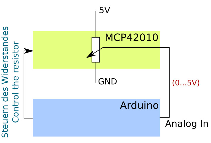
The idea is to switch the two digital 10 kilohms potentiometers at the ends between 5 volts and ground and place the center of each potentiometer on an individual analog input.
Depending on what now for a resistor controlled, the voltage at the analog inputs will rise or fall. And this can be evaluated.
I describe how I proceeded.
I’ve been used an Arduino Nano replica, which is already available for a little more than 3.50 Euros, and a digital potentiometer MCP42010 (data sheet), which I ordered for about 2 euros at www.reichelt.de.
I have also tested the design with a Arduino Uno and the same IO pins. Successful :-)
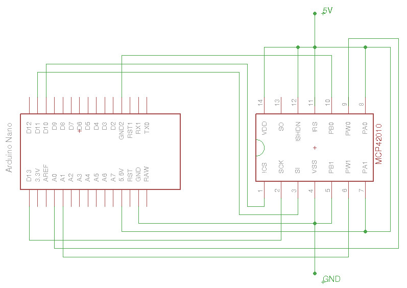
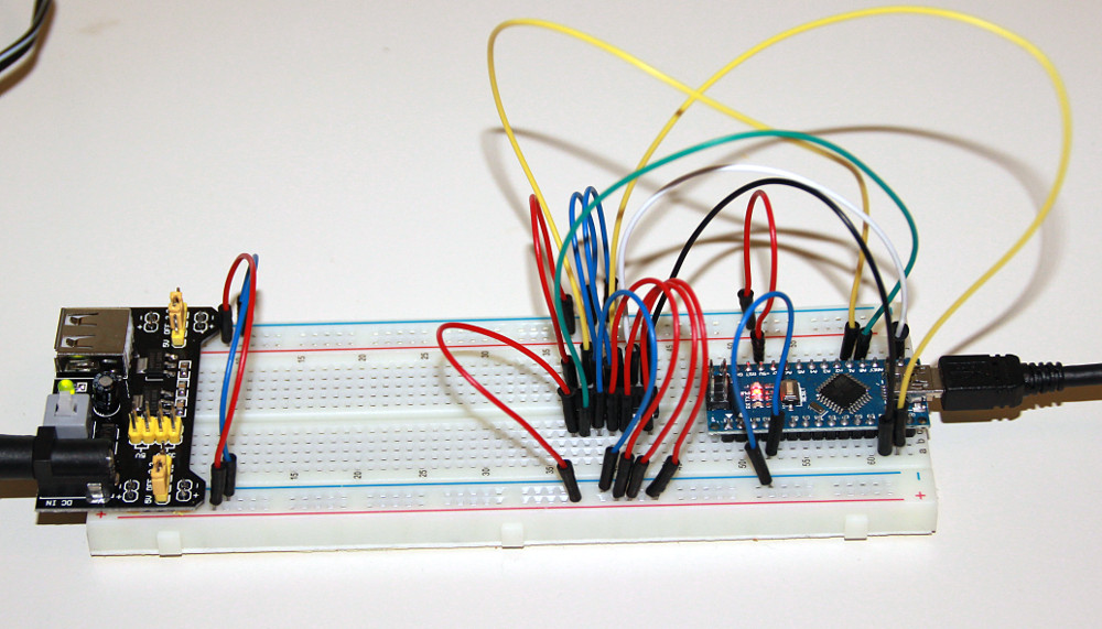
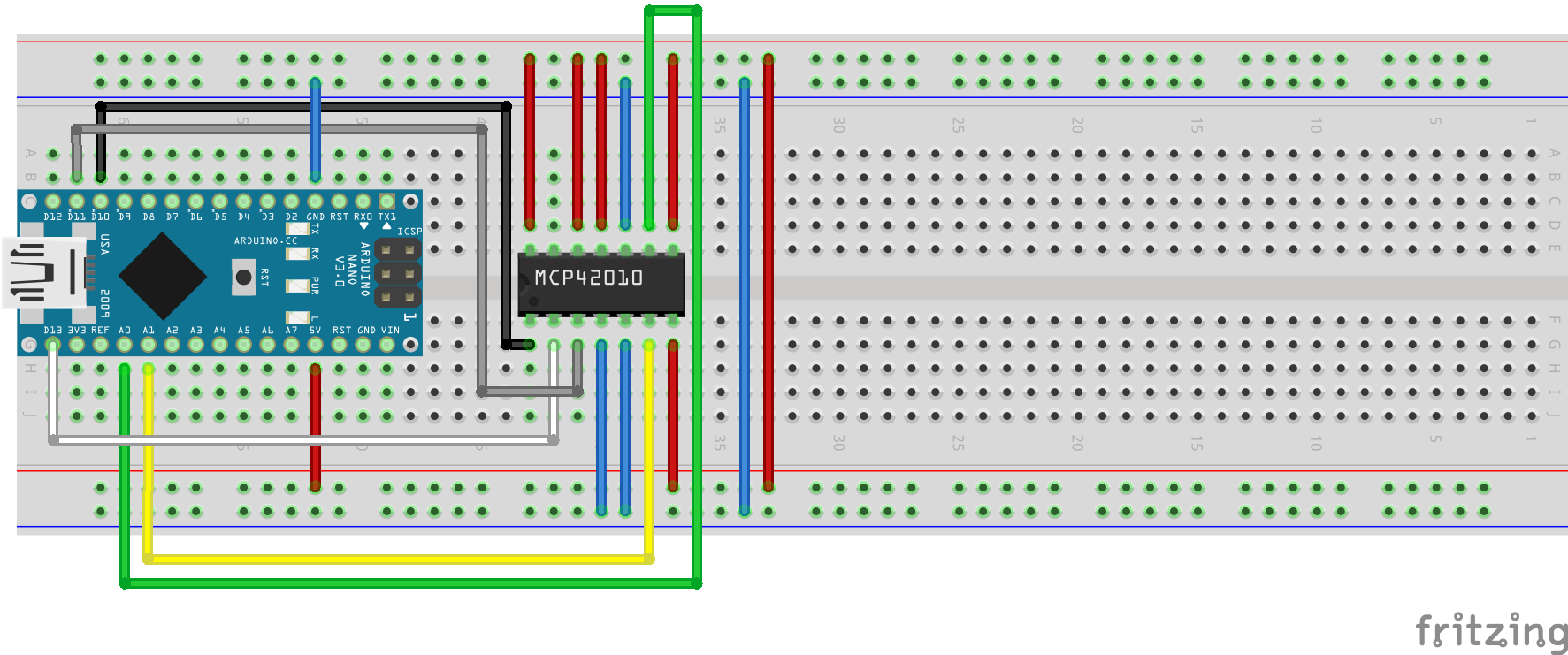
As shown in the following Fritzing image and the Eagle circuit diagram, I have wired as follows.
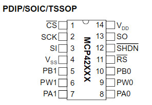 MCP42010:
Pin 1 -> D10 Arduino, Pin2 -> D13 Arduino, Pin3 -> D11 Arduino, Pin4 -> GND, Pin5 -> GND, Pin6 -> A1 -> Arduino, Pin7 -> +5V, Pin8 -> + 5V, Pin9 -> A0 Arduino, Pin10 -> GND, Pin11 -> +5V, Pin12 -> 5V, Pin13 – free, Pin14 -> 5V
Arduino: In addition to the connections at MCP42010, I had to connect only 5 Volt and ground at the Arduino to supply them with power.
Control of the MCP42010
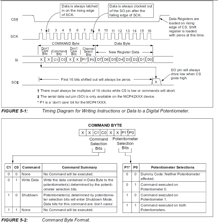 As shown in the data sheet on page 18, CS (PIN 10) must be set to Low for the duration of the transmission.
2 bytes are sent for transmission.
First, a control byte, specifying the operation (write) and the pot (the desired one of the two potentiometers).
Write to potentiometer 1 -> B00010001 and to potentiometer 2 -> B00010010
The second byte is the value that the selected potentiometer should take up.
Here is a minimal example, as in the potentiometer 1 (Pot0) the value 127, thus approximate middle position is loaded.
//minimal Example to set the Pot0 of a MCP42010 to the value 127
#include
void setup() {
  // take the CS pin low to select the chip:
  digitalWrite(10,LOW);
  //  send in the address and value via SPI:
  SPI.transfer(B00010001);
  // write out the value 127
  SPI.transfer(127);
  // take the CS pin high to de-select the chip:
  digitalWrite(10,HIGH);
}

void loop() {

}
The program for ‘comfortable’ control of the 2 potentiometers of the MCP42010
The operation is very simple, as was already seen in the video above. I pass values to the digital potentiometer and evaluate the resulting voltage at the analog inputs A0 and A1.
For the data input and output I use the serial monitor of the Arduino IDE.
data input:
1:Value between 0-255 -> sets potentiometer1 to the value and returns the voltage to A0
2:Value between 0-255 -> sets potentiometer2 to the value and returns the voltage to A1
s -> returns values for both potentiometers and the voltages at the Pins A0 and A1
// inslude the SPI library:
#include

// set pin 10 as the slave select for the digital pot:
const int slave_Select_Pin  = 10;
const int analogInPin0      = A0;
const int analogInPin1      = A1;
String    inputString       = "";         // a string to hold incoming data
boolean   stringComplete    = false;      // whether the string is complete
int       level1            = 0;
int       level2            = 0;

void setup() {
     inputString.reserve(100);
     // set the slaveSelectPin as an output:
     pinMode (slave_Select_Pin, OUTPUT);
     Serial.begin(9600);

     // initialize SPI:
     SPI.begin();
     MSP42010PotWrite(slave_Select_Pin, B00010001, level1);
     MSP42010PotWrite(slave_Select_Pin, B00010010, level2);
}

void loop() {
  if (stringComplete) {
    //check ob R1:
    if (inputString.substring(0, 2) == "1:") {
      level1 = inputString.substring(2).toInt();
      MSP42010PotWrite(slave_Select_Pin, B00010001, level1);
      printValues(level1, analogInPin0);
    }
    //check ob R2:
    if (inputString.substring(0, 2) == "2:") {
      level2 = inputString.substring(2).toInt();
      MSP42010PotWrite(slave_Select_Pin, B00010010, level2); //Datasheet Page 18
      printValues(level2, analogInPin1);
    }
    //check ob s
    if (inputString.substring(0, 1) == "s") {
      printValues(level1, analogInPin0);
      printValues(level2, analogInPin1);
    }
    // clear the string:
    inputString = "";
    stringComplete = false;
  }
}

void MSP42010PotWrite(int slaveSelectPin, byte address, int value) {
     // take the SS pin low to select the chip:
     digitalWrite(slaveSelectPin,LOW);
     //  send in the address and value via SPI:
     SPI.transfer(address);
     SPI.transfer(value);
     // take the SS pin high to de-select the chip:
     digitalWrite(slaveSelectPin,HIGH);
}
void printValues(int level, int aPin) {
      delay(5);
      int pot = 0;
      if (aPin == 15) {
        pot = 1;
      }
      Serial.print("level Pot");
      Serial.print(pot);
      Serial.print(": ");
      Serial.print(level);
      Serial.print(" Spannung an A");
      Serial.print(pot);
      Serial.print(": ");
      double sl = analogRead(aPin);
      sl = sl * 5 / 1024;
      Serial.print(sl);
      Serial.println(" Volt");
}
/*
  SerialEvent occurs whenever a new data comes in the
 hardware serial RX.  This routine is run between each
 time loop() runs, so using delay inside loop can delay
 response.  Multiple bytes of data may be available.
 */
void serialEvent() {
  while (Serial.available()) {
    // get the new byte:
    char inChar = (char)Serial.read();
    // add it to the inputString:
    // if the incoming character is a newline, set a flag
    // so the main loop can do something about it:
    if (inChar == '\n') {
      stringComplete = true;
    } else {
      inputString += inChar;
    }
  }
}
3 replies on “Arduino MCP42010 – control and test the digital potentiometer”
Prima, vielen Dank! Hat auf Anhieb funktioniert!
Glaubst du es wäre möglich diesen digital angesteuerten Widerstand für den Expression-Pedal-Eingang eines Guitar Pedals zu verwenden?
Schon möglich. Dafür kenne ich mich mit ‘Guitar Pedals’ zu wenig aus.