Categories
Node Red

Arduino – Node Red – MCP42010 control the digital potentiometer

Arduino – Node Red – MCP42010 – Sample control of the digital potentiometer

In the article Arduino – control and test digital potentiometer MCP42010 on a breadboard I showed how the MCP42010 can be controlled via the serial monitor of the Arduino IDE.
Now I want to do this more comfortably.
The operation has to take place from the browser, should look visually very appealing and it must also be possible with the smartphone.

Why with Node Red?

Node Red is included in the standard installation of the Raspberry Pi, free and intuitive to use.
By the possibility of clicking together the flow by drag and drop together, one comes very quickly to a good result.
For prototypes and also IOT applications this is a really great thing.
Where light is, is also shadow: Node Red consumes quite a lot of resources.
Nevertheless, the Raspberry Pi 2 does well and the performance with the Pi 3 should still much better.

Required functions of the flow

The flow is supposed to take over the entries, which I have done by hand in the Arduino – control and test digital potentiometer MCP42010 on a breadboard.
The flow should represent the return values in a Gauge Chart.

data input:
1:Value between 0-255
-> sets potentiometer1 to the value and returns the voltage to A0
2:Value between 0-255
-> sets potentiometer2 to the value and returns the voltage to A1

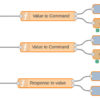
The Flow

  • copy the following flow and insert it under menu (top right) -> Import – Clipboard
[{"id":"ebf0e947.110038","type":"ui_slider","z":"8ec3bd3.cce4dc","tab":"147200e2.b8e19f","name":"Slider","topic":"","group":"Pot1","order":1,"min":0,"max":"255","x":225.5,"y":125,"wires":[["25bd2695.9acaf2"]]},{"id":"b755b484.2bd75","type":"ui_text","z":"8ec3bd3.cce4dc","tab":"147200e2.b8e19f","name":"Wert","group":"Pot1","order":1,"format":"{{msg.payload}}","x":636.5,"y":102,"wires":[]},{"id":"ed9f01b2.dfae38","type":"ui_gauge","z":"8ec3bd3.cce4dc","tab":"147200e2.b8e19f","name":"Spannung in V an A0","group":"Pot1","order":1,"format":"{{value}}","min":0,"max":"5","x":681.5,"y":322,"wires":[]},{"id":"25bd2695.9acaf2","type":"function","z":"8ec3bd3.cce4dc","name":"Value to Command","func":"var msg1 = { payload:\"1:\" + msg.payload +\"\\n\"};\nreturn [msg, msg1];","outputs":"2","noerr":0,"x":440.5,"y":125,"wires":[["b755b484.2bd75"],["134514.6c0042ed"]]},{"id":"134514.6c0042ed","type":"serial out","z":"8ec3bd3.cce4dc","name":"/dev/ttyUSB0","serial":"d535ccdc.123838","x":658.5,"y":148,"wires":[]},{"id":"13db30d1.da3c67","type":"serial in","z":"8ec3bd3.cce4dc","name":"/dev/ttyUSB0","serial":"43aa993f.185738","x":186.5,"y":345,"wires":[["f39416bc.0495"]]},{"id":"f39416bc.0495","type":"function","z":"8ec3bd3.cce4dc","name":"Response to value","func":"//find A0 or A1\nvar value;\nif (msg.payload.indexOf(\"A0\") != -1) {\n    value = msg.payload.split(\"A0: \");\n    value = value[1].replace(\" Volt\", \"\");\n    msg.payload = value;\n    return [msg, null];\n} else {\n    value = msg.payload.split(\"A1: \");\n    value = value[1].replace(\" Volt\", \"\");\n    msg.payload = value;\n    return [null , msg];\n}","outputs":"2","noerr":0,"x":431.5,"y":345,"wires":[["ed9f01b2.dfae38"],["ddbfff6.2bdb3"]]},{"id":"8a48ef7d.33ba9","type":"ui_slider","z":"8ec3bd3.cce4dc","tab":"147200e2.b8e19f","name":"Slider","topic":"","group":"Pot2","order":1,"min":0,"max":"255","x":224,"y":227,"wires":[["127d632d.c0419d"]]},{"id":"5a58be54.e6b8d8","type":"ui_text","z":"8ec3bd3.cce4dc","tab":"147200e2.b8e19f","name":"Wert","group":"Pot2","order":1,"format":"{{msg.payload}}","x":635,"y":204,"wires":[]},{"id":"127d632d.c0419d","type":"function","z":"8ec3bd3.cce4dc","name":"Value to Command","func":"var msg1 = { payload:\"2:\" + msg.payload +\"\\n\"};\nreturn [msg, msg1];","outputs":"2","noerr":0,"x":439,"y":227,"wires":[["5a58be54.e6b8d8"],["ee1b0407.9fbca"]]},{"id":"ee1b0407.9fbca","type":"serial out","z":"8ec3bd3.cce4dc","name":"/dev/ttyUSB0","serial":"43aa993f.185738","x":657,"y":250,"wires":[]},{"id":"ddbfff6.2bdb3","type":"ui_gauge","z":"8ec3bd3.cce4dc","tab":"147200e2.b8e19f","name":"Spannung in V an A1","group":"Pot2","order":1,"format":"{{value}}","min":0,"max":"5","x":681,"y":370,"wires":[]},{"id":"147200e2.b8e19f","type":"ui_tab","z":"","name":"Test MCP42010","icon":"dashboard","order":"1"},{"id":"d535ccdc.123838","type":"serial-port","z":"","serialport":"/dev/ttyUSB0","serialbaud":"9600","databits":"8","parity":"none","stopbits":"1","newline":"\\n","bin":"false","out":"char","addchar":false},{"id":"43aa993f.185738","type":"serial-port","z":"","serialport":"/dev/ttyUSB0","serialbaud":"9600","databits":"8","parity":"none","stopbits":"1","newline":"\\n","bin":"false","out":"char","addchar":false}]

Video Controlling MCP42010 with Node Red

Categories
Arduino

Arduino MCP42010 – control and test the digital potentiometer

Arduino MCP42010 – test on a breadboard

There are many instructions to control digital potentiometers with an Arduino. The search for the MCP42010, was very promising, but led to success only after several attempts. Many web pages and foren entries discuss the topic, but in the end they do not come to a working solution.

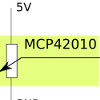
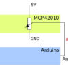
The idea is to switch the two digital 10 kilohms potentiometers at the ends between 5 volts and ground and place the center of each potentiometer on an individual analog input.
Depending on what now for a resistor controlled, the voltage at the analog inputs will rise or fall. And this can be evaluated.

I describe how I proceeded.

I’ve been used an Arduino Nano replica, which is already available for a little more than 3.50 Euros, and a digital potentiometer MCP42010 (data sheet), which I ordered for about 2 euros at www.reichelt.de.
I have also tested the design with a Arduino Uno and the same IO pins. Successful :-)

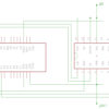
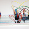
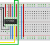
As shown in the following Fritzing image and the Eagle circuit diagram, I have wired as follows.
Pin relation MCP42010MCP42010:
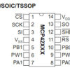
Pin 1 -> D10 Arduino, Pin2 -> D13 Arduino, Pin3 -> D11 Arduino, Pin4 -> GND, Pin5 -> GND, Pin6 -> A1 -> Arduino, Pin7 -> +5V, Pin8 -> + 5V, Pin9 -> A0 Arduino, Pin10 -> GND, Pin11 -> +5V, Pin12 -> 5V, Pin13 – free, Pin14 -> 5V

Arduino: In addition to the connections at MCP42010, I had to connect only 5 Volt and ground at the Arduino to supply them with power.

Control of the MCP42010

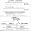
MCP42010 datasheet excerptAs shown in the data sheet on page 18, CS (PIN 10) must be set to Low for the duration of the transmission.
2 bytes are sent for transmission.
First, a control byte, specifying the operation (write) and the pot (the desired one of the two potentiometers).
Write to potentiometer 1 -> B00010001 and to potentiometer 2 -> B00010010
The second byte is the value that the selected potentiometer should take up.
Here is a minimal example, as in the potentiometer 1 (Pot0) the value 127, thus approximate middle position is loaded.

//minimal Example to set the Pot0 of a MCP42010 to the value 127 
#include 
void setup() {
  // take the CS pin low to select the chip:
  digitalWrite(10,LOW);
  //  send in the address and value via SPI:
  SPI.transfer(B00010001);
  // write out the value 127
  SPI.transfer(127);
  // take the CS pin high to de-select the chip:
  digitalWrite(10,HIGH);
}
 
void loop() {
 
}

The program for ‘comfortable’ control of the 2 potentiometers of the MCP42010

The operation is very simple, as was already seen in the video above. I pass values to the digital potentiometer and evaluate the resulting voltage at the analog inputs A0 and A1.
For the data input and output I use the serial monitor of the Arduino IDE.

data input:
1:Value between 0-255 -> sets potentiometer1 to the value and returns the voltage to A0
2:Value between 0-255 -> sets potentiometer2 to the value and returns the voltage to A1
s -> returns values for both potentiometers and the voltages at the Pins A0 and A1

// inslude the SPI library:
#include 
 
// set pin 10 as the slave select for the digital pot:
const int slave_Select_Pin  = 10;
const int analogInPin0      = A0; 
const int analogInPin1      = A1; 
String    inputString       = "";         // a string to hold incoming data
boolean   stringComplete    = false;      // whether the string is complete
int       level1            = 0;
int       level2            = 0;
 
void setup() {
     inputString.reserve(100);
     // set the slaveSelectPin as an output:
     pinMode (slave_Select_Pin, OUTPUT);
     Serial.begin(9600);
 
     // initialize SPI:
     SPI.begin();
     MSP42010PotWrite(slave_Select_Pin, B00010001, level1);
     MSP42010PotWrite(slave_Select_Pin, B00010010, level2);
}
 
void loop() {
  if (stringComplete) {
    //check ob R1:
    if (inputString.substring(0, 2) == "1:") {
      level1 = inputString.substring(2).toInt();
      MSP42010PotWrite(slave_Select_Pin, B00010001, level1);     
      printValues(level1, analogInPin0);
    }
    //check ob R2:
    if (inputString.substring(0, 2) == "2:") {
      level2 = inputString.substring(2).toInt();
      MSP42010PotWrite(slave_Select_Pin, B00010010, level2); //Datasheet Page 18
      printValues(level2, analogInPin1);
    }
    //check ob s
    if (inputString.substring(0, 1) == "s") {
      printValues(level1, analogInPin0);
      printValues(level2, analogInPin1);
    }
    // clear the string:
    inputString = "";
    stringComplete = false;
  }
}
 
void MSP42010PotWrite(int slaveSelectPin, byte address, int value) {
     // take the SS pin low to select the chip:
     digitalWrite(slaveSelectPin,LOW);
     //  send in the address and value via SPI:
     SPI.transfer(address);
     SPI.transfer(value);
     // take the SS pin high to de-select the chip:
     digitalWrite(slaveSelectPin,HIGH);
}
void printValues(int level, int aPin) {
      delay(5);
      int pot = 0;
      if (aPin == 15) {
        pot = 1;
      }
      Serial.print("level Pot");
      Serial.print(pot);
      Serial.print(": ");
      Serial.print(level);
      Serial.print(" Spannung an A");
      Serial.print(pot);
      Serial.print(": ");
      double sl = analogRead(aPin);
      sl = sl * 5 / 1024; 
      Serial.print(sl);
      Serial.println(" Volt");  
}
/*
  SerialEvent occurs whenever a new data comes in the
 hardware serial RX.  This routine is run between each
 time loop() runs, so using delay inside loop can delay
 response.  Multiple bytes of data may be available.
 */
void serialEvent() {
  while (Serial.available()) {
    // get the new byte:
    char inChar = (char)Serial.read();
    // add it to the inputString:
    // if the incoming character is a newline, set a flag
    // so the main loop can do something about it:
    if (inChar == '\n') {
      stringComplete = true;
    } else {
      inputString += inChar;
    }
  }
}
Categories
Raspberry Pi

Raspberry Pi – using the serial interface (RS232)

The Raspberry Pi is equipped with many interfaces.
And the possibilities can rise more than exponentially by using of the USB port.
But to communicate with AVR microcontrollers is the best suited way by using a serial interface.
Of course, the Raspberry Pi A has a serial interface, but unfortunately merely as pins on the GPIO connector.

The required pins, could be connected theoretically directly to the microcontroller eg. ATMega8.
But that would require that the microcontroller operates at 3.3 volts.
My Pollin evaluation board works with 5 volts, but is made with a complete RS232 interface for communication with PC or other equipment.
The easiest way would it be, when the Pi would have an RS232 interface like a PC with the same connectors and signal levels.
By Googling I’ve found the website Serial Port Add On.
The described Serial Port to TTL Digital Converter Module there, I’ve bought at Ebay.

GPIO Header Pins
RaspberryPI_GPIO_serielle_Schnittstelle
2 4 6 8 10 12 14 16 18 20 22 24 26
1 3 5 7 9 11 13 15 17 19 21 23 25
1= 3.3V, 9= GND, 8= TX, 10= RX

The jumper cables to connect to the Raspberry Pi were included in the delivery.
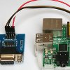
I’ve connected the module with the Pi, as shown in the picture below.

To get the serial interface up and running, are some changes in/etc/inittab and /boot/cmdline.txt necessary.

/etc/inittab

  • comment line: ‘T0:23:respawn:/sbin/getty -L ttyAMA0 115200 vt100’
#Spawn a getty on Raspberry Pi serial line
#T0:23:respawn:/sbin/getty -L ttyAMA0 115200 vt100

/boot/cmdline.txt

  • delete of: dwc_otg.lpm_enable=0 console=ttyAMA0,115200 kgdboc=ttyAMA0,115200 console=tty1 root=/dev/mmcblk0p2 rootfstype=ext4 elevator=deadline rootwait
dwc_otg.lpm_enable=0 console=tty1 root=/dev/mmcblk0p2 rootfstype=ext4 elevator=deadline rootwait

pictures of my PI inclusive ‘serial device’

RaspberryPI_mit_serieller_Schnittstelle_VS RaspberryPI_GPIO_serielle_Schnittstelle1_VS RaspberryPI_GPIO_serielle_Schnittstelle2_VS RaspberryPI_GPIO_serielle_Schnittstelle3_VS RaspberryPI_GPIO_serielle_Schnittstelle4_VS

Video, for Demonstration

The video is already on my ‘Hello World Example’ in the ATMega8 area of my website in use.

For that I’ve written a little perl script. Surely it is possible to use programs like minicom, but I dont wanted to spend the time to familiarize myself with a new tool.
The script was written faster and from my perspective it’s much more flexible for further use and for experiments.

Categories
ATMega8

(Deutsch) ATMega8 – Registerinhalte auf dem Mikrocontroller über serielle Schnittstelle steuern

Sorry, this entry is only available in German.

selfmade Wooden Generator 1 – Experiment 2 with rectifier

Wooden Generator 1 with rectifier

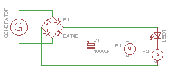
Based on Wooden Generator Experiment 1, the circuit was now extended by a bridge rectifier.

For this I used BAT48 Schottky diodes because they consume only 0.2 volts.
A 1000 μF electrolytic capacitor is used as a stabilizing element.
The capacitor buffers the whole a little and the LED should light up longer and more stable.
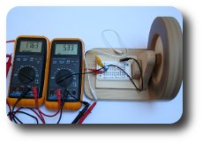
With a small LED as a consumer, I get a current of approx. 5 mA and a voltage of approx. 1.7 V with fast speeds.
The result is a proud performance of 8.5 milliwatts.
So there is still much room for improvement :-)

Wooden Generator Schaltplan Experiment 2 Wooden Generator Versuchsaufbau Exeperiment 2

The following video gives a brief impression of the rather poor yield.

https://youtube.com/watch?v=SH9jxq0oGrw%26hl%3Den%26fs%3D1

(Deutsch) Wooden Generator 1 – Experiment 1

Sorry, this entry is only available in German.

Categories
ATMega8

(Deutsch) ATMega8 – LED 1 und 2 über Taster T1 und T2 schalten

Sorry, this entry is only available in German.

Categories
measurement and control

(Deutsch) Drehzahlmessung und Datenerfassung durch Videobeweis

Sorry, this entry is only available in German.

selfmade VAWT vertical axis windmill – lenz 2 turbine

selfmade VAWT

On these pages, I am about to document the construction of a vertical axis wind turbine.

So far here I have always logged my activities, when I have worked on it.

more detailed information you can find on this pages:

As a first impression here times a video, which shows the wind wheel in operation.

It is a vertical – axis wind turbine based on the model of a Lenz2.

Categories
measurement and control

(Deutsch) 002 – automatisierte Verbrauchsgenerierung und Messung

Sorry, this entry is only available in German.