Geany dark Editor – configure an alternate dark color theme
general
My applications running under Ubuntu (As of today 1/2017 Version 14.10) with the window manager Unity and the Ubuntu standard GTK + theme Ambiance.
It is possible to select different styles in Unity, but the dark themes are looking not so nice across all applications.
Especially with the Internet browsers, I think dark themes are not suitable.
However, it is possible to start applications with individual selected ‘color’ themes.
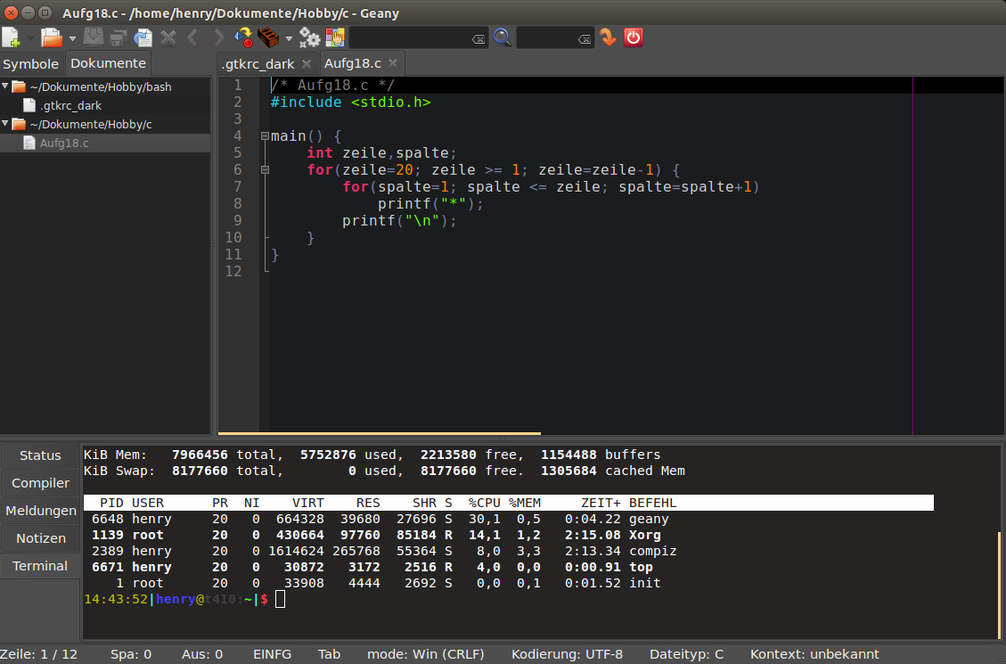
In order to let geany look as shown in the picture further below, I proceeded as follows.
step by step
- install geany, if not already present -> sudo apt-get install geany
editor internal
- If there should be no color themes available in geany, download them here: https://github.com/geany/geany-themes/
- copy the folder colorschemes into ~/.config/geany/
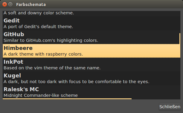
- now you can choose in geany from View -> Editor -> Color Themes – Color Themes your preferred Theme
I use ‘raspberry’.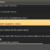
Editor outside area
As described in http://www.henrykoch.de/de/eclipse-programmierumgebung-dunkel-machen, I build on an existing dark GTK+ theme and have modified this for me.
The following informations I stored as file .gtkrc_dark in ~/home/…/ (choose a convinient place for you)
gtk-color-scheme = "base_color:#252525\nfg_color:#f0f0f0\ntooltip_fg_color:#252525\nselected_bg_color:#FFD587\nselected_fg_color:#252525\ntext_color:#dadada\nbg_color:#4d4d4d\ntooltip_bg_color:#FFA500\nlink_color:#494949"
style "gtkcompact" {
	font_name="Sans 11"
	GtkButton::default_border={0,0,0,0}
	GtkButton::default_outside_border={0,0,0,0}
	GtkButtonBox::child_min_width=0
	GtkButtonBox::child_min_heigth=0
	GtkButtonBox::child_internal_pad_x=0
	GtkButtonBox::child_internal_pad_y=0
	GtkMenu::vertical-padding=1
	GtkMenuBar::internal_padding=0
	GtkMenuItem::horizontal_padding=4
	GtkToolbar::internal-padding=0
	GtkToolbar::space-size=0
	GtkOptionMenu::indicator_size=0
	GtkOptionMenu::indicator_spacing=0
	GtkPaned::handle_size=4
	GtkRange::trough_border=0
	GtkRange::stepper_spacing=0
	GtkScale::value_spacing=0
	GtkScrolledWindow::scrollbar_spacing=0
	GtkExpander::expander_size=10
	GtkExpander::expander_spacing=0
	GtkTreeView::vertical-separator=0
	GtkTreeView::horizontal-separator=0
	GtkTreeView::expander-size=8
	GtkTreeView::fixed-height-mode=TRUE
	GtkWidget::focus_padding=0

	####################
	# Color Definitions
	####################

	bg[NORMAL]= @bg_color
	bg[PRELIGHT]  = shade (1.02, @bg_color)
	bg[SELECTED]  = @selected_bg_color
	bg[INSENSITIVE]   = shade (0.95, @bg_color)
	bg[ACTIVE]= shade (0.9, @bg_color)
	fg[NORMAL]= @fg_color
	fg[PRELIGHT]  = @fg_color
	fg[SELECTED]  = @selected_fg_color
	fg[INSENSITIVE]   = darker (@bg_color)
	fg[ACTIVE]= @fg_color
	text[NORMAL]  = @text_color
	text[PRELIGHT]= @text_color
	text[SELECTED]= @selected_fg_color
	text[INSENSITIVE] = shade (0.8, @bg_color)
	text[ACTIVE]  = darker (@text_color)
	base[NORMAL]  = @base_color
	base[PRELIGHT]= shade (0.98, @bg_color)
	base[SELECTED]= @selected_bg_color
	base[INSENSITIVE] = shade (0.97, @bg_color)
	base[ACTIVE]  = shade (0.94, @bg_color)

}

class "GtkWidget" style "gtkcompact"
style "gtkcompactextra" {
	xthickness=0
	ythickness=0
}

class "GtkButton" style "gtkcompactextra"
class "GtkToolbar" style "gtkcompactextra"
class "GtkPaned" style "gtkcompactextra"
To start, I still need a bash script:
#!/bin/sh
export GTK2_RC_FILES="/home/.../.gtkrc_dark"
geany $1
env --unset=GTK2_RC_FILES
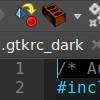
In addition, I have built a small dark geany logo and also stored under /home/…/ . (the 3 files as zip file geanydarkfiles.zip)
The last action must be performed with root privileges: sudo gedit /usr/share/applications/geany.desktop
Adjust the following two entries:
Exec=/home/.../geany.sh %F
Icon=/home/.../geany.xpm
Now Geany can always be called in dark, without having to start it from a console so it becomes dark.