The Raspberry Pi is equipped with many interfaces.
And the possibilities can rise more than exponentially by using of the USB port.
But to communicate with AVR microcontrollers is the best suited way by using a serial interface.
Of course, the Raspberry Pi A has a serial interface, but unfortunately merely as pins on the GPIO connector.
The required pins, could be connected theoretically directly to the microcontroller eg. ATMega8.
But that would require that the microcontroller operates at 3.3 volts.
My Pollin evaluation board works with 5 volts, but is made with a complete RS232 interface for communication with PC or other equipment.
The easiest way would it be, when the Pi would have an RS232 interface like a PC with the same connectors and signal levels.
By Googling I’ve found the website Serial Port Add On.
The described Serial Port to TTL Digital Converter Module there, I’ve bought at Ebay.
| GPIO Header Pins | ||||||||||||
|---|---|---|---|---|---|---|---|---|---|---|---|---|
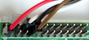 |
||||||||||||
| 2 | 4 | 6 | 8 | 10 | 12 | 14 | 16 | 18 | 20 | 22 | 24 | 26 |
| 1 | 3 | 5 | 7 | 9 | 11 | 13 | 15 | 17 | 19 | 21 | 23 | 25 |
| 1= 3.3V, 9= GND, 8= TX, 10= RX | ||||||||||||
The jumper cables to connect to the Raspberry Pi were included in the delivery.
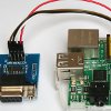
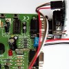
I’ve connected the module with the Pi, as shown in the picture below.
To get the serial interface up and running, are some changes in/etc/inittab and /boot/cmdline.txt necessary.
/etc/inittab
- comment line: ‘T0:23:respawn:/sbin/getty -L ttyAMA0 115200 vt100’
#Spawn a getty on Raspberry Pi serial line
#T0:23:respawn:/sbin/getty -L ttyAMA0 115200 vt100
/boot/cmdline.txt
- delete of: dwc_otg.lpm_enable=0
console=ttyAMA0,115200 kgdboc=ttyAMA0,115200console=tty1 root=/dev/mmcblk0p2 rootfstype=ext4 elevator=deadline rootwait
dwc_otg.lpm_enable=0 console=tty1 root=/dev/mmcblk0p2 rootfstype=ext4 elevator=deadline rootwait
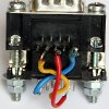
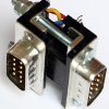
pictures of my PI inclusive ‘serial device’
Video, for Demonstration
The video is already on my ‘Hello World Example’ in the ATMega8 area of my website in use.
For that I’ve written a little perl script. Surely it is possible to use programs like minicom, but I dont wanted to spend the time to familiarize myself with a new tool.
The script was written faster and from my perspective it’s much more flexible for further use and for experiments.



6 replies on “Raspberry Pi – using the serial interface (RS232)”
Guten Tag,
ich habe alles so gemacht, wie beschrieben. Wenn ich in screen oder minicom was tippe, kommt alles im Terminalprogramm (Windows 8 – TeraTerm oder auch HyperTerm) an. Wenn ich auf der Windowsseite tippe, kommt am Pi nichts an. Was mache ich falsch??
Mein Fernziel ist, meine Wintergartensteuerung (mit -Control I von Conrad) zu überwachen und evtl. nach Absturz neu zu starten. Dafür sendet die SPS jede Minute eine Protokollzeile in die Serielle Schnittstelle.
M.f.G. Erich Baars
Hallo Herr Baars,
leider kenne ich mich mit Windows 8 nicht aus.
Ist es möglich mit einem anderen PC oder Laptop etwas an die Raspberry PI zu senden?
In den Terminalprogrammen lässt sich ja so einiges einstellen, wie Baudrate, Data Bits, Stop Bits, Handshake, etc.
Sind diese Werte auf der Windows Seite genau so wie auf der PI Seite?
Ich habe gerade mal Cutecom gestartet und sehe z.B. dass es auch die Möglichkeit gib die Verbindung nur lesend zu erlauben.
Grüsse Henry
Ein altes Nokia Datenkabel DKU-5 oder CA-42 liefert die erforderliche Spannung von 3,3V. Diese bekommt man für wenige Euro.
Hallo Herr Bensel,
habe gerade mal gegoogelt und bin u.a. bei http://www.nokiaport.de fündig geworden.
Das ist auf jeden Fall eine Option.
Einen Pegelwandler von 3,3 auf 5Volt und umgekehrt hinzubekommen, sollte theoretisch auch mit einem Transistor und 2 Widerstaänden machbar sein.
Das RX Signal zur Pi muss über einen Widerstand gedämpft werden, so dass maximal 40mA Strom fließen können.
Das TX Signal von der Pi geht mit einem Vorwiderstand an die Basis eines Transitors und über den Kollektorkreis wird die 5 Volt Seite des Evaluationsboards gesteuert.
Das ist mal ein Mini Projekt für den Winter :-)
Grüsse Henry
Du, reicht die Stromversorgung vom Pi aus um keine kleine Optolink-Schaltung (IR-Diode/Fotozelle) zu versorgen? Da die andere Seite eh nur optisch angebunden ist brauch ich ja keinen Pegelwandler.
Es gibt Optokoppler die mit einigen hundert uA oder noch weniger auskommen. Allerdings würde ich einen einfachen Level Shifter empfehlen. Die sind oft open Drain und können so für fast jede Spannungsübersetzung angewendet werden.