Categories
Python

Raspberry Pi – Access to WordPress with Python wordpress-api

Would not it be nice if the Raspberry Pi could create articles on my website, modify them and become an editor?
If you use WordPress on your website, it’s relatively easy, since WordPress from version 4.8 includes the REST interface as standard and there is a corresponding plugin for older versions.

Whether the interface is available, can be easily detected by attaching ‘wp-json’ to the URL for each WordPress web page. For example, http://www.henrykoch.de/wp-json should display a Json string in the browser:

"name":"www.HenryKoch.de","description":"","url":"http:\/\/www.henrykoch.de","home":"http:\/\/www.henrykoch.de\/de","gmt_offset":2,"timezone_string":"Europe\/Berlin"

Installation python wordpress-api

For the installation of the WordPress Api for python, I am followed this guide https://pypi.python.org/pypi/wordpress-api/1.2.2, which did not work immediately.
To get the API running, additional packages had to be installed.

So I came to the result (On the Raspberry Pi)

sudo apt-get update
sudo apt-get install libxml2-dev
sudo apt-get build-dep python3-lxml
pip install wordpress-api

Libxml and lxml were missing from me.

Authentication

I spent a lot of time here.
I really wanted an OAuth authentication and I failed with the described REST oauth1 plugin.
After a long back and forth I installed this plugin: WP OAuth Server

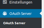
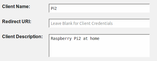
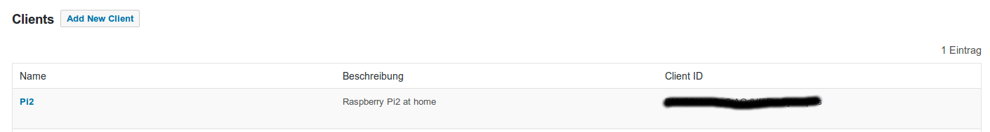
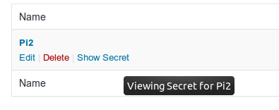
As seen on the pictures, there is an OAuth server entry after installation on the dashboard on the left side. There I created a user. If this is done, the user is listed and a client ID is specified. Consumer_key in the phthon script
In addition, the Secret Key can now be displayed -> consumer_secret in the python script.
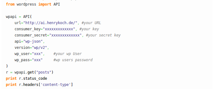
first test script

#!/usr/bin/python
# -*- coding: utf-8 -*-
from wordpress import api as wpapi
from wordpress import API
 
wpapi = API(
    url="http://ai.henrykoch.de/", #your URL
    consumer_key="xxxxxxxxxxxxx", #your key
    consumer_secret="xxxxxxxxxxxxx", #your secret key
    api="wp-json",
    version="wp/v2",
    wp_user="xxx",    #your wp User
    wp_pass="xxx"     #wp users password
)
r = wpapi.get("posts")
print r.status_code
print r.headers['content-type']
print r.encoding
print r.text
print r.json()

The result

pi@raspberrypi:~/python/Wordpress $ python myscript.py
200
application/json; charset=UTF-8
UTF-8
[{"id":1,"date":"2017-08-08T15:25:58","date_gmt":"2017-08-08T13:25:58","guid":{"rendered":"http:\/\/ai.henrykoch.de\/?p=1"},"modified":"2017-08-08T15:38:46","modified_gmt":"2017-08-08T13:38:46","slug":
...
Categories
Node Red

Arduino – Node Red – MCP42010 control the digital potentiometer

Arduino – Node Red – MCP42010 – Sample control of the digital potentiometer

In the article Arduino – control and test digital potentiometer MCP42010 on a breadboard I showed how the MCP42010 can be controlled via the serial monitor of the Arduino IDE.
Now I want to do this more comfortably.
The operation has to take place from the browser, should look visually very appealing and it must also be possible with the smartphone.

Why with Node Red?

Node Red is included in the standard installation of the Raspberry Pi, free and intuitive to use.
By the possibility of clicking together the flow by drag and drop together, one comes very quickly to a good result.
For prototypes and also IOT applications this is a really great thing.
Where light is, is also shadow: Node Red consumes quite a lot of resources.
Nevertheless, the Raspberry Pi 2 does well and the performance with the Pi 3 should still much better.

Required functions of the flow

The flow is supposed to take over the entries, which I have done by hand in the Arduino – control and test digital potentiometer MCP42010 on a breadboard.
The flow should represent the return values in a Gauge Chart.

data input:
1:Value between 0-255
-> sets potentiometer1 to the value and returns the voltage to A0
2:Value between 0-255
-> sets potentiometer2 to the value and returns the voltage to A1

The Flow

  • copy the following flow and insert it under menu (top right) -> Import – Clipboard
[{"id":"ebf0e947.110038","type":"ui_slider","z":"8ec3bd3.cce4dc","tab":"147200e2.b8e19f","name":"Slider","topic":"","group":"Pot1","order":1,"min":0,"max":"255","x":225.5,"y":125,"wires":[["25bd2695.9acaf2"]]},{"id":"b755b484.2bd75","type":"ui_text","z":"8ec3bd3.cce4dc","tab":"147200e2.b8e19f","name":"Wert","group":"Pot1","order":1,"format":"{{msg.payload}}","x":636.5,"y":102,"wires":[]},{"id":"ed9f01b2.dfae38","type":"ui_gauge","z":"8ec3bd3.cce4dc","tab":"147200e2.b8e19f","name":"Spannung in V an A0","group":"Pot1","order":1,"format":"{{value}}","min":0,"max":"5","x":681.5,"y":322,"wires":[]},{"id":"25bd2695.9acaf2","type":"function","z":"8ec3bd3.cce4dc","name":"Value to Command","func":"var msg1 = { payload:\"1:\" + msg.payload +\"\\n\"};\nreturn [msg, msg1];","outputs":"2","noerr":0,"x":440.5,"y":125,"wires":[["b755b484.2bd75"],["134514.6c0042ed"]]},{"id":"134514.6c0042ed","type":"serial out","z":"8ec3bd3.cce4dc","name":"/dev/ttyUSB0","serial":"d535ccdc.123838","x":658.5,"y":148,"wires":[]},{"id":"13db30d1.da3c67","type":"serial in","z":"8ec3bd3.cce4dc","name":"/dev/ttyUSB0","serial":"43aa993f.185738","x":186.5,"y":345,"wires":[["f39416bc.0495"]]},{"id":"f39416bc.0495","type":"function","z":"8ec3bd3.cce4dc","name":"Response to value","func":"//find A0 or A1\nvar value;\nif (msg.payload.indexOf(\"A0\") != -1) {\n    value = msg.payload.split(\"A0: \");\n    value = value[1].replace(\" Volt\", \"\");\n    msg.payload = value;\n    return [msg, null];\n} else {\n    value = msg.payload.split(\"A1: \");\n    value = value[1].replace(\" Volt\", \"\");\n    msg.payload = value;\n    return [null , msg];\n}","outputs":"2","noerr":0,"x":431.5,"y":345,"wires":[["ed9f01b2.dfae38"],["ddbfff6.2bdb3"]]},{"id":"8a48ef7d.33ba9","type":"ui_slider","z":"8ec3bd3.cce4dc","tab":"147200e2.b8e19f","name":"Slider","topic":"","group":"Pot2","order":1,"min":0,"max":"255","x":224,"y":227,"wires":[["127d632d.c0419d"]]},{"id":"5a58be54.e6b8d8","type":"ui_text","z":"8ec3bd3.cce4dc","tab":"147200e2.b8e19f","name":"Wert","group":"Pot2","order":1,"format":"{{msg.payload}}","x":635,"y":204,"wires":[]},{"id":"127d632d.c0419d","type":"function","z":"8ec3bd3.cce4dc","name":"Value to Command","func":"var msg1 = { payload:\"2:\" + msg.payload +\"\\n\"};\nreturn [msg, msg1];","outputs":"2","noerr":0,"x":439,"y":227,"wires":[["5a58be54.e6b8d8"],["ee1b0407.9fbca"]]},{"id":"ee1b0407.9fbca","type":"serial out","z":"8ec3bd3.cce4dc","name":"/dev/ttyUSB0","serial":"43aa993f.185738","x":657,"y":250,"wires":[]},{"id":"ddbfff6.2bdb3","type":"ui_gauge","z":"8ec3bd3.cce4dc","tab":"147200e2.b8e19f","name":"Spannung in V an A1","group":"Pot2","order":1,"format":"{{value}}","min":0,"max":"5","x":681,"y":370,"wires":[]},{"id":"147200e2.b8e19f","type":"ui_tab","z":"","name":"Test MCP42010","icon":"dashboard","order":"1"},{"id":"d535ccdc.123838","type":"serial-port","z":"","serialport":"/dev/ttyUSB0","serialbaud":"9600","databits":"8","parity":"none","stopbits":"1","newline":"\\n","bin":"false","out":"char","addchar":false},{"id":"43aa993f.185738","type":"serial-port","z":"","serialport":"/dev/ttyUSB0","serialbaud":"9600","databits":"8","parity":"none","stopbits":"1","newline":"\\n","bin":"false","out":"char","addchar":false}]

Video Controlling MCP42010 with Node Red

Categories
Raspberry Pi

USB over IP, extend the network, Wifi – to use Arduino over Raspberry Pi as gateway

USB over IP – First contact point:

Actions on the server side – Raspberry Pi

USB over IP is to be available on the Raspberry Pi from kernel Linux 3.17 without further installation.

Check what kernel I have:

17:45:46|pi@raspberrypi:~|$ uname -r
4.1.13+

Kernel version is higher :-)
Test:

17:49:05|pi@raspberrypi:~|$ usbip
-bash: usbip: Command not found.

That’s not much good. :-(

Continue with the tips from the forum: https://www.raspberrypi.org/forums/viewtopic.php?p=121691

install usbip

17:49:25|pi@raspberrypi:~|$ sudo apt-get install usbip

loading the Kernel module

17:54:16|pi@raspberrypi:~|$ sudo modprobe usbip-host

Starting the usbip daemon

08:52:50|pi@raspberrypi:~|$ sudo usbipd -D

listing USB devices (without Arduino)

18:01:48|pi@raspberrypi:~|$ lsusb
Bus 001 Device 002: ID 0424:9512 Standard Microsystems Corp. 
Bus 001 Device 001: ID 1d6b:0002 Linux Foundation 2.0 root hub
Bus 001 Device 003: ID 0424:ec00 Standard Microsystems Corp.

and listing USB devices (with Arduino plugged in)

18:02:30|pi@raspberrypi:~|$ lsusb
Bus 001 Device 002: ID 0424:9512 Standard Microsystems Corp. 
Bus 001 Device 001: ID 1d6b:0002 Linux Foundation 2.0 root hub
Bus 001 Device 003: ID 0424:ec00 Standard Microsystems Corp. 
Bus 001 Device 005: ID 1a86:7523 QinHeng Electronics HL-340 USB-Serial adapter

In my case is the ID of the USB device: 1a86:7523
The same again with the program usbip

18:05:21|pi@raspberrypi:~|$ sudo usbip list -l
Local USB devices
=================
 - busid 1-1 (0424:9512)
         1-1:1.0 -> hub
 
 - busid 1-1.1 (0424:ec00)
         1-1.1:1.0 -> smsc95xx
 
 - busid 1-1.2 (1a86:7523)
         1-1.2:1.0 -> ch341

Binding of the USB device

09:22:48|pi@raspberrypi:~/deb_pakete|$ sudo usbip bind -b 1-1.2
bind device on busid 1-1.2: complete

Actions on the client side – in my case a laptop with Ubuntu

Install usbip

Take a look at: https://wiki.ubuntuusers.de/USBIP/

sudo apt-get install linux-tools-generic

loading Kernel module

10:06:22|henry@t410:~/deb_pakete|$ sudo modprobe vhci-hcd
10:08:30|henry@t410:~/deb_pakete|$ lsmod | grep vhci
vhci_hcd               33435  0 
usbip_core             27617  1 vhci_hcd

Listing the USB devices that are provided on the PI

10:11:10|henry@t410:~/deb_pakete|$ sudo usbip list -r 192.xxx.xxx.xxx
Exportable USB devices
======================
 - 192.xxx.xxx.xxx
      1-1.2: QinHeng Electronics : HL-340 USB-Serial adapter (1a86:7523)
           : /sys/devices/platform/bcm2708_usb/usb1/1-1/1-1.2
           : Vendor Specific Class / unknown subclass / unknown protocol (ff/00/00)
           :  0 - Vendor Specific Class / unknown subclass / unknown protocol (ff/01/02)

adding the USB Device

10:24:20|henry@t410:~/deb_pakete|$ sudo usbip attach -h 192.xxx.xxx.xxx -b 1-1.2
10:24:45|henry@t410:~/deb_pakete|$ lsusb
Bus 003 Device 002: ID 1a86:7523 QinHeng Electronics HL-340 USB-Serial adapter

Check with the Arduino IDE

USB over IP Arduiono Remote programmiert über IP

Actions on the server side – Raspberry Pi

After using on the server side – releasing the USB device

09:22:54|pi@raspberrypi:~/deb_pakete|$ sudo usbip unbind -b 1-1.2
unbind device on busid 1-1.2: complete
Categories
Python

Raspberry Pi – Python – SQLite database – a simple frugal way to manage data professionally

The following post provides code examples in Python inclusive the complete sources for download

  1. Create a new SQLite database
  2. Create a new table
  3. Display of all tables in a database
  4. Insert values into a table
  5. View table contents
  6. Code to download

0 Preliminary two links to SQLite descriptions / tutorials

1 Create a new SQLite database

To create a database it’s enough to make a connect to a non-existing database and the database file will be created automatically.

#!/usr/bin/python
# -*- coding: utf-8 -*-
 
import sqlite3 as lite
import sys
 
def create_new_database(PfadzurDatenbank):
    try:
        con = lite.connect(PfadzurDatenbank) 
        con.commit()
 
    except lite.Error, e:
        if con:
            con.rollback()
            print "Error %s:" % e.args[0]
            sys.exit(1)
 
    finally:
        if con:
            con.close() 
 
create_new_database("/home/pi/sqlite3/BeispielDatenbank.db")
pi@raspberrypi ~/sqlite3 $ ls -al
insgesamt 580
drwxr-xr-x  2 pi pi   4096 Okt 21 10:02 .
drwxr-xr-x 12 pi pi   4096 Sep 27 20:26 ..
-rw-r--r--  1 pi pi      0 Okt 21 10:02 BeispielDatenbank.db

2 Create a new table

In the following code example, a table will be created, which will be used to store the measured values of a temperature sensor DS18820.
The table consists of three columns

  • time stamp
  • minimum temperature
  • maximum temperature

The goal for this table is to insert timestamps and temperature values. Each
row stands for a timeframe of one hour. The temperatures which are measured within the hour, will be compared to the maximum and minimum values that already stored in the table.
Bildschirmfoto vom 2015-10-21 11:14:11

If the new value is greater than the maximum value at the table, it will be replaced. If the new value is less than minimum value in the table, the minimum value will be replaced.
So regardless of the number of measurements (greater than 1) remain three values per hour (timestamp, MinTemp, MaxTemp), which is perfectly adequate for a normal measurement of space or outdoor temperatures.

#!/usr/bin/python
# -*- coding: utf-8 -*-
 
import sqlite3 as lite
import sys
 
def create_new_temperature_sensor_table(PathToDatabase, TableName):
    try:
        con = lite.connect(PathToDatabase)
        cur = con.cursor()  
        cur.executescript("""
            CREATE TABLE %s(    Timestamp INT PRIMARY KEY, 
                                Temp_MIN REAL, 
                                Temp_MAX REAL); 
            """ % TableName) 
        con.commit()
 
    except lite.Error, e:
 
        if con:
            con.rollback()
 
            print "Error %s:" % e.args[0]
            sys.exit(1)
 
    finally:
 
        if con:
            con.close() 
create_new_temperature_sensor_table("/home/pi/sqlite3/BeispielDatenbank.db", "Fuehler1")

3 Display of all tables in a database

Currently, only one table (Fuehler1) in the database was created, which can be displayed by using the following script.

#!/usr/bin/python
# -*- coding: utf-8 -*-
 
import sqlite3 as lite
import sys
def list_all_tables_in_DB(PathToDatabase):
    try:
        con = lite.connect(PathToDatabase)
 
        with con:
 
            cur = con.cursor()    
            cur.execute("SELECT name FROM sqlite_master WHERE type='table'")
 
            rows = cur.fetchall()
 
            for row in rows:
                print row[0]
 
    except lite.Error, e:
 
        if con:
            con.rollback()
 
            print "Error %s:" % e.args[0]
            sys.exit(1)
 
    finally:
 
        if con:
            con.close() 
 
list_all_tables_in_DB("/home/pi/sqlite3/BeispielDatenbank.db")
pi@raspberrypi ~/python_scripts $ python DB_Funktionen.py 
Fuehler1

4 Insert values into a table

The following is to be inserted into the table Fuehler1:

  • Timestamp: 1445432400
  • Temp_MIN: 15.0
  • Temp_MAX: 17.22
#!/usr/bin/python
# -*- coding: utf-8 -*-
 
import sqlite3 as lite
import sys
 
def insert_new_line_in_temperature_sensor_table(PathToDatabase, TableName, 
                                                Timestamp, Temp_MIN, Temp_MAX):
 
    try:
        con = lite.connect(PathToDatabase)
        cur = con.cursor()  
        cur.execute("""
            INSERT INTO %s 
            VALUES( %i , %.3f, %.3f)
            """ % (TableName, Timestamp, Temp_MIN, Temp_MAX))
        con.commit()
 
    except lite.Error, e:
 
        if con:
            con.rollback()
 
            print "Error %s:" % e.args[0]
            sys.exit(1)
 
    finally:
 
        if con:
            con.close() 
 
insert_new_line_in_temperature_sensor_table("/home/pi/sqlite3/BeispielDatenbank.db", 
                                            "Fuehler1", 1445432400, 15.0, 17.22)

5 View table contents

#!/usr/bin/python
# -*- coding: utf-8 -*-
 
import sqlite3 as lite
import sys
 
def show_all_table_entries(PathToDatabase, TableName):
    try:
        con = lite.connect(PathToDatabase)
        cur = con.cursor()  
        cur.execute("SELECT * FROM %s" % TableName)
        lines = cur.fetchall()
        for line in lines:
            print line
        con.commit()
 
    except lite.Error, e:
        if con:
            con.rollback()
            print "Error %s:" % e.args[0]
            sys.exit(1)
 
    finally:
        if con:
            con.close()
show_all_table_entries("/home/pi/sqlite3/BeispielDatenbank.db", "Fuehler1")
pi@raspberrypi ~/python_scripts $ python DB_Funktionen.py 
(1445432400, 15.0, 17.22)

6 Code to download

download: DB_Funktionen.py

Categories
Raspberry Pi

Raspberry Pi – configure automatically daily restart / reboot with cron

A nice thing is the ability to perform actions automatically to defined times with the cron daemon.

A helpful introduction about cron can be found here: https://www.raspberrypi.org/documentation/linux/usage/cron.md
Those like me who has difficulty to use with vi, can be pleased, because the necessary command to configure sudo crontab -e opens the nano editor.

Should, for example, the Raspberry Pi do every day at 14:44 clock a healthy reboot, you have to add following to the crontab of the root user (with sudo).

17:10:33|pi@raspberrypi:~|$ sudo crontab -e
# For more information see the manual pages of crontab(5) and cron(8)
#
# m h  dom mon dow   command
44 14 * * * /sbin/shutdown -r now

Now, the system should make every day at 14:44 o clock a reboot.

Categories
Python

(Deutsch) Raspberry Pi – Python – (HC-SR04) Ultraschall Abstandsmessung – fehlerhafte Ergebnisse durch Statistik in den Griff bekommen – Teil1

Sorry, this entry is only available in German.

Categories
Python

Python – remove oldest files in a directory, only a defined count of them remains

By experimenting with the Pi camera and PIR at may Raspberry Pi were quickly many images written to the SD card.

In order to get some control, the following Python Script is a good basis.
There is the possibility to specify a directory and the maximum number of files stored in it.

Exceeds the number of files the defined value, older files are deleted.

In my case, I always keep a maximum of 1000 images in the folder.

Sample code:

#!/usr/bin/python
 
import os
 
path = "/home/pi/pictures/"
max_Files = 1000
 
def sorted_ls(path):
    mtime = lambda f: os.stat(os.path.join(path, f)).st_mtime
    return list(sorted(os.listdir(path), key=mtime))
 
del_list = sorted_ls(path)[0:(len(sorted_ls(path))-max_Files)]
 
for dfile in del_list:
    os.remove(path + dfile)
Categories
Raspberry Pi

Raspberry Pi – homemade level converter for serial communication rs232 3.3 volts to 5 volts TTL for AVR microcontroller

I found that the Raspberry Pi serial interface rs232, described in a older post by myself, was too bulky.

Pi and AVR should be connected through a less amount of wires.

So I’ve searched the best hints to solder a cheap and uncomplicated level converter, that can directly be connected between the GPIO of the Pi and the rx/tx pins of the microcontroller.

On the German website http://www.elektronik-kompendium.de/sites/praxis/bausatz_pegelwandler-mit-transistoren.htm I found a useful circuit with transistors and resistors that I had in my toolbox. (something similar but also matching parts)

The following images are showing my circuit diagram and the test setup.

The first test worked flawlessly both in the direction to the Pi and in the direction to AVR microcontroller.

Eigenbau_Pegelwandler_2Eigenbau_PegelwandlerSchaltplan_Pegelwandler_Raspberry_Pi_TTLEigenbau_Pegelwandler_3

The third picture shows the circuit diagram used and the fourth image the development on breadboard. Now I can connect my test board and the Pi over normal jumper cable to have hanging around without various additional boards.

Categories
Raspberry Pi

Raspberry Pi – using the serial interface (RS232)

The Raspberry Pi is equipped with many interfaces.
And the possibilities can rise more than exponentially by using of the USB port.
But to communicate with AVR microcontrollers is the best suited way by using a serial interface.
Of course, the Raspberry Pi A has a serial interface, but unfortunately merely as pins on the GPIO connector.

The required pins, could be connected theoretically directly to the microcontroller eg. ATMega8.
But that would require that the microcontroller operates at 3.3 volts.
My Pollin evaluation board works with 5 volts, but is made with a complete RS232 interface for communication with PC or other equipment.
The easiest way would it be, when the Pi would have an RS232 interface like a PC with the same connectors and signal levels.
By Googling I’ve found the website Serial Port Add On.
The described Serial Port to TTL Digital Converter Module there, I’ve bought at Ebay.

GPIO Header Pins
RaspberryPI_GPIO_serielle_Schnittstelle
2 4 6 8 10 12 14 16 18 20 22 24 26
1 3 5 7 9 11 13 15 17 19 21 23 25
1= 3.3V, 9= GND, 8= TX, 10= RX

The jumper cables to connect to the Raspberry Pi were included in the delivery.
I’ve connected the module with the Pi, as shown in the picture below.

To get the serial interface up and running, are some changes in/etc/inittab and /boot/cmdline.txt necessary.

/etc/inittab

  • comment line: ‘T0:23:respawn:/sbin/getty -L ttyAMA0 115200 vt100’
#Spawn a getty on Raspberry Pi serial line
#T0:23:respawn:/sbin/getty -L ttyAMA0 115200 vt100

/boot/cmdline.txt

  • delete of: dwc_otg.lpm_enable=0 console=ttyAMA0,115200 kgdboc=ttyAMA0,115200 console=tty1 root=/dev/mmcblk0p2 rootfstype=ext4 elevator=deadline rootwait
dwc_otg.lpm_enable=0 console=tty1 root=/dev/mmcblk0p2 rootfstype=ext4 elevator=deadline rootwait

pictures of my PI inclusive ‘serial device’

RaspberryPI_mit_serieller_Schnittstelle_VS RaspberryPI_GPIO_serielle_Schnittstelle1_VS RaspberryPI_GPIO_serielle_Schnittstelle2_VS RaspberryPI_GPIO_serielle_Schnittstelle3_VS RaspberryPI_GPIO_serielle_Schnittstelle4_VS

Video, for Demonstration

The video is already on my ‘Hello World Example’ in the ATMega8 area of my website in use.

For that I’ve written a little perl script. Surely it is possible to use programs like minicom, but I dont wanted to spend the time to familiarize myself with a new tool.
The script was written faster and from my perspective it’s much more flexible for further use and for experiments.

Categories
Raspberry Pi

Raspberry Pi – via UMTS into the internet – configuration | setup

RaspberryPi_A_UMTS_D
Raspberry Pi Model A connected via UMTS!

I’ve bought a relatively cheap, used ‘MEDIONmobile’ UMTS stick on Ebay and I’ve separately purchased a ‘Aldi Talk Starter Pack’ at a German Aldi market.

Aldi offers a tariff with 150MB UMTS speed and thereafter GPRS speed, for 3.99€ a month with a possibility to cancel the contract monthly.
It will ‘only’ used the E-Plus network, but that is relatively well available on my location.

short summary: what was necessary to go online?

  1. install wvdial
  2. modify /etc/wvdial.conf
  3. creating a Batch script with 2 lines, to set the SIM card password
  4. customize /etc/network/interfaces
  5. open connection

1. install wvdial

pi@raspberrypi - $ sudo apt-get install wvdial
.
.
Success!  You can run "wvdial" to connect to the internet.
  (You can also change your configuration by editing /etc/wvdial.conf)
 
pi@raspberrypi - $

2. modify /etc/wvdial.conf

For this, a little bit of preliminary work is necessary.
It is important to know something about the path through which the UMTS device will be addressed.
After plugging the stick – enter the command ‘lsusb’ to see whether the key has been detected.

pi@raspberrypi ~ $ lsusb
Bus 001 Device 005: ID 12d1:1003 Huawei Technologies Co., Ltd. E220 HSDPA Modem / E230/E270/E870 HSDPA/HSUPA Modem
pi@raspberrypi ~ $

Attention: In the Raspberry Pi Model B it didn’t work to insert the stick directly into the Pi, since my power supply wasn’t strong enough. (I’ve used a 5Volt 700mA power supply.)
But the operation via a USB hub went smoothly.
The Model A can handle it, probably because they self consumes by default less power.

The last entries in /var/log/messages, will show the path through which the UMTS modem is added.
In my case: /dev/ttyUSB0.

Feb 20 15:17:26 raspberrypi kernel: [   10.527167] usb 1-1.3: new high-speed USB device number 5 using dwc_otg
.
.
Feb 20 15:17:26 raspberrypi kernel: [   11.313066] usbcore: registered new interface driver option
Feb 20 15:17:26 raspberrypi kernel: [   11.323480] USB Serial support registered for GSM modem (1-port)
Feb 20 15:17:26 raspberrypi kernel: [   11.334289] option 1-1.3:1.0: GSM modem (1-port) converter detected
Feb 20 15:17:26 raspberrypi kernel: [   11.345030] usb 1-1.3: GSM modem (1-port) converter now attached to ttyUSB0
Feb 20 15:17:26 raspberrypi kernel: [   11.354849] option 1-1.3:1.1: GSM modem (1-port) converter detected
Feb 20 15:17:26 raspberrypi kernel: [   11.375418] usb 1-1.3: GSM modem (1-port) converter now attached to ttyUSB1

Now I’ve configured the /etc/wvdial.conf for my ‘Aldi – Medionmobile’ access.

pi@raspberrypi /etc $ cat wvdial.conf 
[Dialer Defaults]
Phone = 
Username = 
Password = 
New PPPD = yes
 
[Dialer eplus]
Modem = /dev/ttyUSB0
Phone = *99#
Username = eplus
Password = gprs
Init3 = AT+CGDCONT=1,"IP","internet.eplus.de","0.0.0.0"
ISDN=0
Auto Reconnect=on
Stupid Mode=off
Idle Seconds=0
Auto DNS=on

3. creating a Batch script with 2 lines, to set the SIM card password

Who has secured the SIM card with a PIN, must ensure that the UMTS modem knows these PIN, before dialing.
Therefore serves the following bash script:

pi@raspberrypi /usr/local/bin $ sudo cat setPIN.sh
#!/bin/sh
echo "AT+CPIN=4711\n\r" > /dev/ttyUSB0

And now make sure so that only Root may have a look inside.

pi@raspberrypi /usr/local/bin $ ls -al
insgesamt 352
-rwx--x--x  1 root staff     50 Feb 24 13:14 setPIN.sh

4. /etc/network/interfaces anpassen

Finally, 4 lines coming into the /etc/network/interfaces.

pi@raspberrypi - $ sudo cat /etc/network/interfaces ab auto ppp0
auto lo
 
iface lo inet loopback
iface eth0 inet dhcp
 
auto ppp0
iface ppp0 inet wvdial
provider eplus
pre-up /usr/local/bin/setPIN.sh
 
allow-hotplug wlan0
iface wlan0 inet manual
wpa-roam /etc/wpa_supplicant/wpa_supplicant.conf
iface default inet dhcp

pre-up /usr/local/bin/setPIN.sh -> refers to the script for PIN transfer.

5. open connection

The connection builds up automatically immediately after booting, assuming that the Stick is plugged.

Independent of the automatically solution, the connection can be established and closed, with the the following commands:

pi@raspberrypi - $ sudo ifup ppp0
pi@raspberrypi - $ sudo ifdown ppp0