
Arduino – MCP42010 – Example of controlling several digital potentiometers
After the example Arduino – control and test digital potentiometer MCP42010 on breadboard and the graphic variant Node Red – Arduino – control digital potentiometer MCP42010 I tested the control of 2 digital potentiometers MCP42010 cascaded.
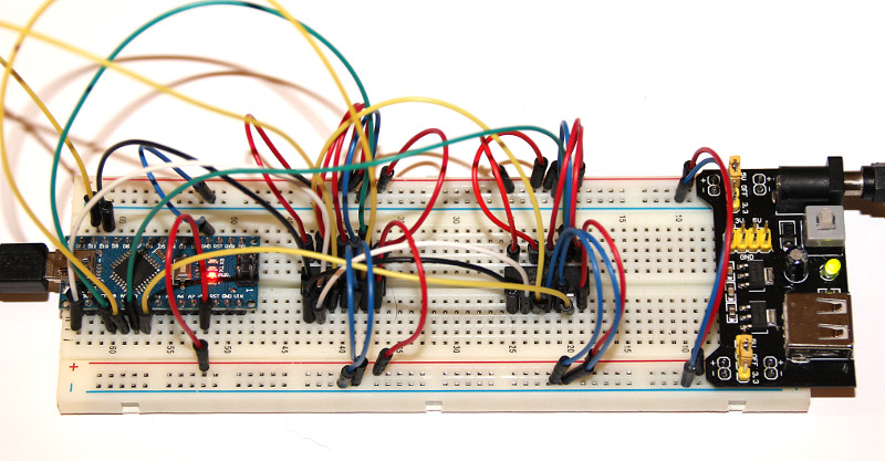
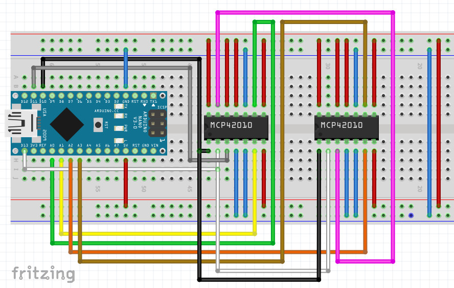
circuit
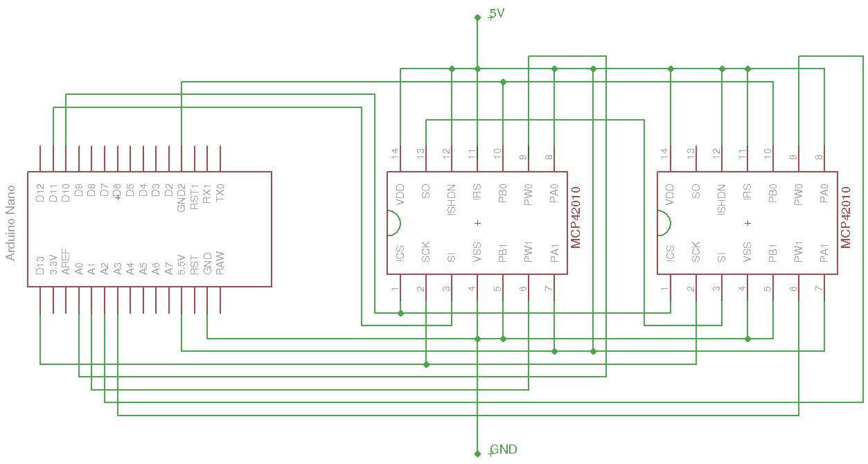
Control of the two MCP42010
 The control of the primary MCP42010 is described in detail in Arduino – Control and Test Digital Potentiometer MCP42010 on breadboard.
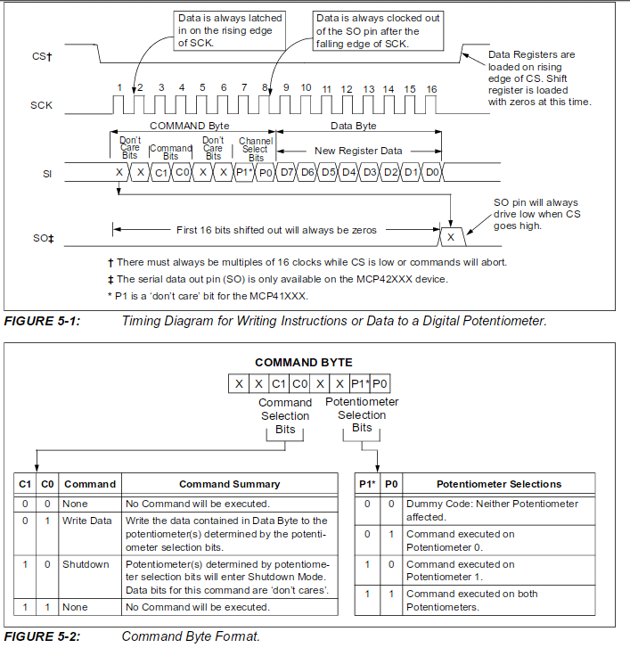
Write in potentiometer 1 -> B00010001 and in potentiometer 2 -> B00010010
The value that the selected potentiometer should set is transmitted as the second byte.
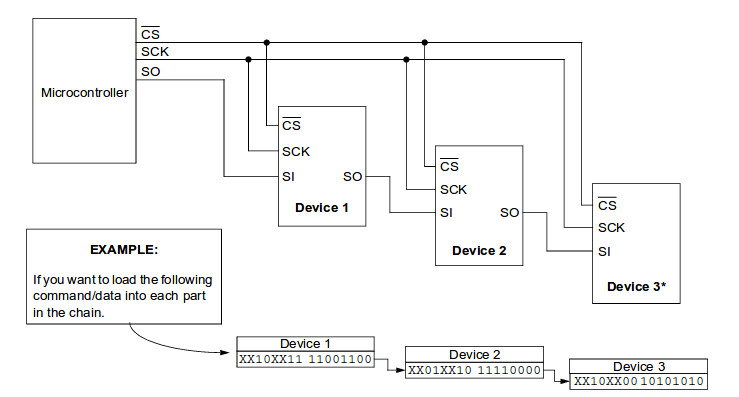
To reach the second MCP42010, 4 bytes have to be sent instead of 2 bytes for a single one.
With three MCP42010 6 bytes are required, with four 8 bytes and so on.
In order to control a potentiometer of the second MCP42010 directly without changing the contents of the first chip, two more bytes with the value 0 are sent.
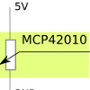
See also the picture on the left from the data sheet.
Write in potentiometer 3 -> B00010001 value B00000000 B00000000
Write in potentiometer 4 -> B00010010 value B00000000 B00000000
The whole thing has to be read from right to left.
4 bytes are written, or better shifted into it.
The first two bytes (from the left) are shifted from the following two bytes into the second MCP42010.
Two bytes with ‘zero’ arrive in the first MCP42010, i.e. no changes to the values in the 1st chip.
Here is a minimal example of how the value 127 is loaded into potentiometer 1 (Pot0) of the second MCP42010.